Losses in a Induction Motor – Power Stages in Asynchronous Motor
Losses, Power Stages and Efficiency of Induction Motor
An induction motor (also known as Asynchronous Motor) is widely used in industries to convert electrical power into mechanical power. Therefore, the input power to the motor is electrical energy. The supplied electrical energy is converted into mechanical energy via various power stages.
For a three-phase induction motor, a three-phase electrical supply is given to the stator. And this supplied power or input power is;
Pin = √3 VL IL cosϕ = 3 Vph Iph Cosϕ
Where,
- VL = line value of supplied voltage
- IL = line value of supplied current
- Vph = phase value of supplied voltage
- Iph = phase value of supplied current
- Cos ϕ = power factor of motor
Related Posts:
- Losses in Synchronous Motor – Power Stages & Efficiency of Synchronous Motors
- Losses in a DC Motor – Power Stages & Efficiency of DC Motor
The losses that occur in induction motor is classified into two types;
- Constant losses
- Variable losses
Constant Losses
The losses that remain constant throughout the operation of the induction motor are known as constant losses. These losses are also known as fixed losses. The constant losses can be determined by performing a no-load test.
The fixed losses are further classified into three types;
- Stator Iron Loss
- Mechanical Loss and Brush Loss e.g. Windage and Friction Losses
Iron Loss
The iron loss (also known as eddy current and hysteresis loss) depends on the supply voltage and its frequency. As the voltage and frequency are practically constant, this loss remains constant during the operation of an induction motor. Iron loss is further divided into two losses; eddy current loss and hysteresis loss.
To minimize the eddy current loss, the laminated core is used. By laminating the core, the area of the core is decreased, and hence the resistance increases which results in decreases in eddy current.
Hysteresis loss mainly depends on the material used for the core. To minimize hysteresis loss, high-grade silicon steel is used.
Core Loss
The core losses depend on frequency. The frequency in a stator is always supply frequency. And the frequency of a rotor is slip times supply frequency. Generally, the slip of an induction motor is 3%. Hence, the rotor frequency is approximately 1.5 Hz. Therefore, the rotor core loss is very small compared to stator core loss and in most conditions, rotor core loss is neglected. The core losses are given by:
PCore = 3E12GC
Related Posts:
- Losses in a DC Generator – Power Stages & Efficiency of DC Generator
- Losses in Alternator – Power Stages & Efficiency of Synchronous Generator
Friction and Windage Loss
Friction and Windage Losses are also known as rotational loss or brush & mechanical loss. This loss depends on the speed of a motor. At the time of starting, this loss is zero. And increases with an increase in speed. Generally, the induction motor operates at a constant speed. Hence, this loss is considered a constant loss.
The losses that occur with the fiction between brushes and commutator is known as brush loss.
Variable Loss = Copper Loss
The losses that are variable throughout the operation of an induction motor are known as variable losses. Generally, the variable loss is also known as copper loss. The copper loss depends on the resistance and current flowing through the winding.
Variable losses in in induction motor are as follows:
- Stator Copper Loss = 3I12R1
- Rotor Copper Loss = 3I22R2
In an induction motor, there are two windings; stator winding and rotor winding. In both windings, copper losses occur due to the winding resistance. The copper loss is directly proportional to the winding resistance and square of the current flowing through the winding. Hence, this loss is also known as I2R loss. To determine the variable loss, a block-rotor test is performed.
In short:
- Stator Losses: The summation of iron loss and copper loss in the stator is known as stator losses. These losses depend on the stator core flux density and supply frequency . The stator losses are almost fixed or constant.
- Rotor Losses: The summation of iron loss and copper loss in the stator is known as stator losses. As the frequency of the rotor current under normal running condition is very small, these kinds of losses are hence negligible. The Rotor Cu. loss of a three phase induction motor can be found using 3I22 R2.
- Friction & Windage Losses: These losses occur due to the friction between shaft and bearings as well as wind barrier is known as friction and windage losses. These losses are also known as rotational losses. Friction and windage losses is directly proportional to the speed of the motor and while core losses is inversely proportional to the speed of the motor.
Related Posts:
- Transformer Losses – Different Types of Losses in a Transformer
- Losses in Electrical Machines – Formulas and Equations
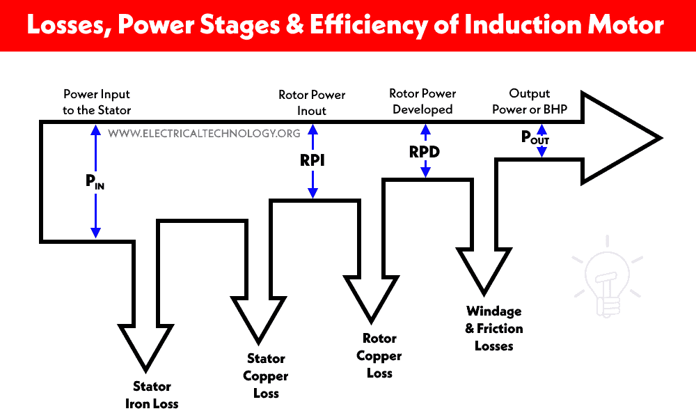
Power Stages of Induction Motor
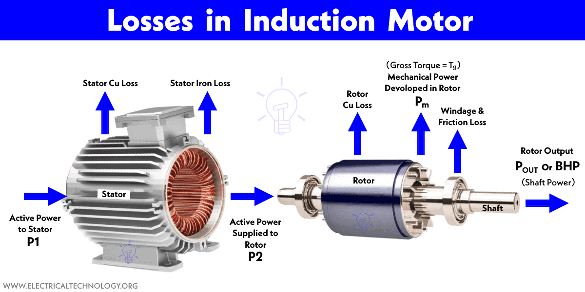
The input of an induction motor is electrical energy and it is supplied to the stator winding. The load is connected with the shaft. Therefore, the mechanical energy (rotational energy) is collected from the shaft. During the conversion of electrical energy into mechanical energy, the power is transferred in losses. The power stages of an induction motor are explained below.

Stage-1 Motor Input (Stator Input)
Stator input (P1) is equal to the summation of power delivered to the rotor or power output of stator and stator losses.
Stator Input P1 = Stator Output + Stator Losses
In stator, two types of losses occur; stator copper loss and stator core loss (iron loss). The output of the stator is given to the rotor. Hence, it becomes rotor input.
Stage-2 Rotor Input
By electromagnetic induction, the stator output is transferred to the rotor via airgap.
Stator Output = Rotor Input P2
Rotor Power Input (RPD) or simply Rotor input (P2) is used to generate mechanical power.
Stage-3 Available Mechanical power
The rotor output is mechanical power (PM) developed in the rotor also known as gross torque (Tg) or RPD (Rotor Power Develop). Due to copper loss in rotor winding, available mechanical power is reduced.
Developed Mechanical Power PM = Rotor Input – Rotor Copper Loss
Stage-4 Mechanical Power at Shaft
The available mechanical power is not entirely transferred to the shaft. There are some frictions and windage losses.
Finally, the mechanical power available at the shaft (POUT) is used to produce shaft torque and this is the final output that is used to rotate the load which is also known as BHP (Brake Horse Power). The graphical repetition of power stages of induction motor is shown in the figure above.
Mechanical Power at Shaft POUT = Available Mechanical Power at shaft – Windage & Friction loss
Related Post:
- What is Motor Efficiency and How to improve it?
- Transformer Efficiency, All day Efficiency & Condition for Maximum Efficiency
Rotor Output
As mentioned in stage 1,
Stator Input = Stator Output + Stator Losses
As the output of the stator transfers to the rotor circuit by electromagnetic induction, hence;
Rotor Input = Stator Output
The rotor output converts in the mechanical energy which is known as gross torque (Tg). Some of the produced torque losses due to windage and friction losses and the net torque appears as shaft torque (Tsh).
Suppose, if the original speed of the rotor is N (in RPS) and the generated torque (Tg) in N.m, then;
Tg × 2π N = Rotor gross output in watts, Pm
Tg = Rotor gross output in watts, Pm ÷ 2π N — N-m … (i)
If there is no copper loss in the rotor, the output of the rotor will be equal to the input of the rotor, hence the motor will run at the synchronous speed (NS).
Tg = Rotor Input P2 ÷ 2π NS — (ii)
Analyzing equation (i) and (ii), we get;
Rotor gross Output = PM = Tg × 2π N
Rotor Input = P2 = Tg × 2π NS — (iii)
The difference between two uniform copper losses
Rotor Copper Losses = P2 – P1 = Tg × 2π (NS – N) — (iv)
Analyzing equation (iii) and (iv), we get;
(Rotor Copper Losses ÷ Rotor Input) = (NS – N ÷ N) = s
And Rotor Copper Losses = Rotor Input × Slip
Hence;
= (NS – N ÷ N) = s = sP2 — (v)
Now, Rotor Gross Output = Rotor Input – Copper Losses
Rotor Gross Output PM = Input P2 – Rotor Copper Losses)
= Input – S × Rotor Input = (1-s) Input P2
= (NS – N ÷ N) = s = sP2 — (v)
∵ Rotor Gross Output PM = (1-s) Rotor Input P2 — (vi)
Hence the Rotor Efficiency will be:
∵ Rotor Efficiency = N ÷ NS
Or
Rotor Cu. Loss ÷ Rotor Gross Output
= S ÷ 1-s
Efficiency of Induction Motor
In general, the efficiency of any system is defined as a ratio of output and input.

The output of an induction motor is mechanical power and hence, for an induction motor, we can write the above formula as follow which is used to determine the efficiency of an induction motor;

Related Posts:
- Types of Electric Motors – Classification of AC, DC & Special Motors
- Applications of Electric Motors
- Single-Phase Induction Motor – Construction, Working, Types & Applications
- Three-Phase Induction Motor – Construction, Working, Types & Applications
- Motor Starter – Types of Motor Starters and Motor Starting Methods
- Direct Online Starter – DOL Starter Wiring Diagram for Motors
- Cable Size Calculation for LT & HT Motors
- Speed Control Methods of of a DC Motor
- Torque Equation of Induction Motor
- Equivalent Circuit of Induction Motor
- Torque-Slip and Torque-Speed Characteristics of Induction Motor
- Speed Control of DC Motor – Voltage, Rheostatic & Flux Control Methods
- DC Machine – Construction, Working, Types and Applications
- Servo Motor – Types, Construction, Working, Controlling & Applications
- Brushless DC Motor (BLDC) – Construction, Working Principle & Applications
- Stepper Motor – Types, Construction, Operation & Applications
- What is Motor Efficiency and How to improve it?
- Induction Motor & Linear Induction Motors Formulas & Equations
- What is Motor Generator Set and How Does it Work?
- How to Run a Three-Phase Induction Motor on a Single-Phase Power Supply?
- Power, Voltage and EMF Equation of a DC Motor
- Electrical & Electronics Engineering Formulas & Equations
- Electric Motors Symbols