Hopkinson’s Test – Circuit Diagram, Working and Applications
What is Hopkinson’s Test? Its Circuit Diagram and Operation in Motor Generator Set & Coupling
What is Hopkinson’s Test?
A Hopkinson Test is used to identify the efficiency of two identical electrical machines (Such as Motor-Generator Set also known as coupling of DC Machines) at full load operation. Both machines are connected mechanically coupled on the same shaft. Also, both machines are electrically coupled. One machine operates as a motor and the second machine operates as a generator.
The mechanical output of the first machine (motor) is fed to drive the second machine (generator). Hence, this test is known as a back-to-back test.
The electrical output of the second machine (generator) is used to supply the first machine (motor). Therefore, this test is known as the regenerative test.
Both machines are identical. It means ratings, armature resistance, filed winding resistance and losses are equal for both machines. If we consider an ideal machine (zero loss), the motor-generator pair continuously operate without any supply.
Good to Know: Hankinson’s Test is also known as Back to Back Test, Heat Run Test and Regenerative Test.
In the Hopkinson’s test, the motor-generator set is connected as shown in the figure below.
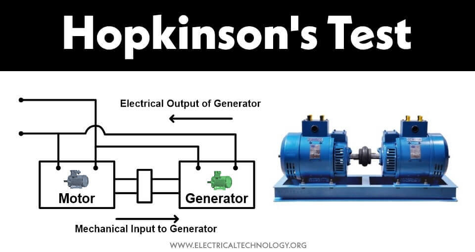
When an electrical input is given to the motor, it starts running. Both machines are connected with the same shaft. Hence, the motor drives the generator. And when the generator rotates on rated speed, it will generate rated electrical output. The electrical output generated by the generator is supplied with the electrical input.
When both machines are running at rated load, the electrical input supplied by the source is equal to the total losses of both machines. As both machines are identical, the losses of both machines are equal. So, the loss of one machine is half of the total loss.
For example, the power required to run this set is 100 W, and the losses of each machine are 15 W.
- Motor output = Motor Input – Motor losses
- Motor output = 100 – 15 = 85 W
- Motor output = Generator input = 85 W
- Generator output = Generator input – Generator losses
- Generator output = 85 – 15
- Generator output = 70 W
70 W output from the generator is supplied to the electrical input. Hence, 30 W is supplied by the input. And this 30 W is losses for both machines. In an actual case, we don’t know the loss of the machine. And we conduct this test to find the losses.
Circuit Diagram of Hopkinson’s Test
The connection diagram for the Hopkinson test is as shown in the figure below. Here, two identical DC machines are connected electrically as well as mechanically.
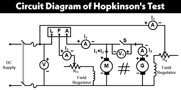
The electrical supply is given to the first machine and this machine behaves as a motor. Initially, switch S is kept open. Hence, the input is supplied to the motor only. The speed of the motor is adjusted to the rated speed with help of a field regulator.
The second machine behaves like a generator. When we give input to the motor, it will start rotating. And both machines are connected on the same shaft. So, the generator generates electrical power. The output of a generator is adjusted to rated power with the help of a field regulator.
Still, the switch S is open. A voltmeter is connected across the switch. When the voltage generated by the generator is the same as the supply voltage, this voltmeter indicates zero reading. And at this stage, close the switch S.
Now the generator will supply to the motor. And the electrical power supplied by the input is used to meet losses of both machines.
When the generator is connected to a motor, the excitation of the generator is increased. It results in to increase in its EMF which becomes greater than the supply voltage. As the motor is loaded, the speed is decreased. The speed of the motor and output voltage of the generator is adjusted by the field regulators.
Observation Table
| Input voltage (V) | Current drawn from the supply
(I1) |
Generator armature current
(I2) |
Motor armature current
(I1+I2) |
Motor field current
(I3) |
Generator field current
(I4) |
| … | … | … | … | … | … |
Calculation of Hopkinson Test
- Input voltage = V
- Current drawn from the supply = I1
- Generator armature current = I2
- Motor armature current = I1 + I2
- Motor field current = I3
- Generator field current = I4
- Armature resistance for motor = Rm
- Armature resistance for generator = Rg
Now,
Power drawn from the supply = VI1
The power drawn from the supply is equal to the losses of both machines. The losses of DC machines are; copper loss, iron loss, and mechanical loss.
Let’s assume the iron and mechanical loss for each machine is Wc.
Armature copper loss for motor;
Pam = (I1 + I2 )2 Rm
Armature copper loss for generator;
Pag = I22 Rg
Now, a sum of all losses is equal to the power drawn from the supply.
VI1 = 2WC + Pam + Pag
VI1 = 2WC + (I1+ I2)2 Rm +I22Rg
Wc = ½ (VI1 – (I1 + I2)2 Rm – I22 Rg
Efficiency of Motor
There are three types of losses in the motor;
- Armature copper loss (Pam)
- Shunt field copper loss (Pfm)
- Iron and mechanical loss (WC)
The current that passes through the shunt field winding is I3.
Hence, shunt field copper loss;
Pfm = VI3
Total loss of motor;
Ptm = WC + Pam + Pfm
Ptm = WC + (I1 + I2 )2 Rm + VI3
Total input power of motor;
Pi = V(I1 + I2) + VI3
Pi = V(I1 + I2 + I3)
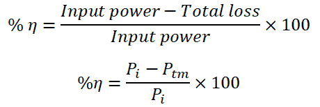
Hence, the efficiency of a motor;
- Related Post: What is Motor Efficiency & How to improve it?
Efficiency of Generator
The current that passes through the field winding of the generator is I4.
Hence, the shunt field copper loss;
Pfg = VI4
Total loss for generator;
Ptg = WC + Pag + Pfg
Ptg = WC + I22 Rg + VI4
The output of generator;
PO = VI2
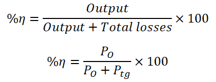
Hence, the efficiency of a generator;
- Related Post: Cable Size Calculation for LT & HT Motors
Advantages & Disadvantages of Hopkinson’s Test
Advantages
The advantages of the Hopkinson test are as listed below.
- The power required to perform this test is very small for large machines. Hence, it is an economical method of testing.
- This test is performed to find the efficiency of the DC machine. By this test, the efficiency of the machine can be found at various load conditions.
- In this test, both machines are operating at rated load conditions. Therefore, the stray load losses are taken into account.
- The temperature rise is also estimated during this test.
Disadvantages
The disadvantages of the Hopkinson test are as listed below.
- In the Hopkinson test, two identical machines are required. And it is very difficult to find two identical machines.
- The excitation of both machines is different. Therefore, it is impossible to separate iron losses.
- Both machines cannot be loaded evenly.
- Because of the variation in field current, it is difficult to operate both machines at rated speed.
Applications of the Hopkinson Test.
As mentioned above, the main purpose of the Hopkinson test is to determine the efficiency of electrical machines especially in case of coupling of motors and generators (also known as Motor-Generator Set) based on the combined iron losses of both machines which can’t be separated.
Related Posts:
- Swinburne’s Test of DC Machines – Circuit and Applications
- No-load Test of Induction Motor – Block Rotor Test of Motor
- Polarity Test of a Transformer – Circuit Diagram and Working
- Sumpner’s Test or Back-to-Back Test on a Transformer
- Short Circuit Test and Open Circuit Test of Transformer
- Losses in a DC Generator – Power Stages & Efficiency of DC Generator
- Losses in a DC Motor – Power Stages & Efficiency of DC Motor
- Losses in Synchronous Motor – Power Stages & Efficiency of Synchronous Motors
- Losses in Alternator – Power Stages & Efficiency of Synchronous Generator
- Losses in a Induction Motor – Power Stages in Asynchronous Motor
- Transformer Losses – Different Types of Losses in a Transformer
- Losses in Electrical Machines – Formulas and Equations
- Motor Starter – Types of Motor Starters and Motor Starting Methods
- Direct Online Starter – DOL Starter Wiring Diagram for Motors
- Voltage And Power Equations of a DC Motor
- AC Drive – Working and Types of Electrical Drives & VFD
- DC Drive – Working and Types of DC Drives