Sumpner’s Test or Back-to-Back Test on a Transformer
Sumpner’s Test or Back-To-Back Test on Transformer for Efficiency, Voltage Regulation, & Heating Effect
The open-circuit test and short circuit test are performed to determine the equivalent circuit parameter. With the help of these tests, we cannot find the temperature rise in a transformer. Because the open-circuit test is examined only core loss and short-circuit test is examined only copper loss. However, the transformer is not subjected concurrently to both losses. Hence, the alternative is Sumpner’s test.
The solution to this problem is the Sumpner’s test. The Sumpner’s test is performed to determine the transformer efficiency, voltage regulation, and heating effect of the transformer under loading conditions. The Sumpner’s test is also known as the back-to-back test as this test consists of two identical transformers connected back-to-back.
In Sumpner’s test, actual loading conditions are simulated without connecting actual load. For a small transformer, it is convenient to connect full-load. But it is difficult to connect full-load in the case of large transformers. Therefore, this test helps to find the important parameters of the transformer. And the Sumpner’s test gives more accurate results compared to open-circuit and short-circuit tests.
Related Posts:
- Open Circuit and Short Circuit Test of a Transformer
- Hopkinson’s Test – Circuit Diagram, Working and Applications
Sumpner’s Test – (Back-to-Back Test)
To perform the Sumpner’s test, two single-phase transformers with identical ratings are required. The experimental circuit diagram of the Sumpner’s test is shown in the figure below.

As shown in the above figure, two identical rating transformers T1 and T2 are connected back-to-back. Here, the primary winding of both transformers is connected in parallel with rated supply voltage and frequency. An ammeter A1, a voltmeter V1, and a wattmeter W1 is connected to the input side.
The secondary winding of both transformers is connected in series with opposite polarities. A voltmeter V2 is connected between both secondary windings to check the polarity opposition. The range of voltmeter V2 must be double the rated secondary voltage. Now, any two terminals of the secondary winding are connected together (here B and C). And if the voltmeter V2 measures zero voltage between the remaining two terminals (A and D), then two windings are connected in series opposition and we can use A and D terminals for further performance. In case, if the voltmeter V2 reads a double value of rated voltage, the secondary windings are connected in the same polarity. To make this connection opposite, terminals A and C are connected together and terminals B and C are used for further performance.
Now, the rated supply is given to the primary winding. The total voltage across secondary winding is zero. Hence, the secondary windings will behave as an open circuit and the current flowing through the secondary winding is zero. Therefore, due to rated voltage in primary and zero current in secondary, the wattmeter W1 measures the iron loss of both transformers.
A low voltage (hardly 5 to 10%) is given to the secondary terminals with the help of a regulatory transformer TR which is excited by the main supply. An ammeter A2 is connected to the secondary side as shown in the figure above. The magnitude of secondary supply is adjusted till the ammeter A2 reads full load secondary current. The secondary current produces full load current to flow in primary winding (by transformer action) and the path of this current is represented as a green dot line. Hence, the transformer behaves like operating on full-load conditions. Therefore, the wattmeter W2 reads the value of full-load copper loss for both transformers.
The reading of measuring devices connected in the circuit of Sumpner’s test is as follows;
- Ammeter A1 = No-load current = 2I0
- Voltmeter V1 = Applied rated input voltage (Primary voltage)
- Wattmeter W1 = Core losses (iron losses) of both transformers = 2Pi
- Ammeter A2 = Full load secondary current of both transformers = 2I2
- Voltmeter V2 = Total voltage across series connection of both secondary windings
- Wattmeter W2 = Full load copper loss of both transformers = 2Pcu
Observation Table
| I1 Amp | V1 Volts | W1 Watt | I2 Amp | V2 Volts | W2 Watt |
| ….. | ….. | ….. | ….. | ….. | ….. |
Related Posts:
- Current Transformers (CT) – Types, Characteristic & Applications
- Potential Transformer (PT)? Types & Working of Voltage Transformers
- Autotransformer – Its Types, Operation, Advantages and Applications
Calculation of Losses
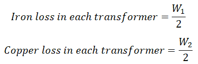
Here, we have connected two identical transformers. Therefore, the losses that occurred in both transformers are the same. The wattmeter (W1 and W2) connected in the circuit measures the iron loss and copper loss for both transformers. So, if you need to find the losses for each transformer, you need to do half the reading.
Calculation of Efficiency
Therefore, the efficiency of a transformer is calculated by;

Calculation of Circuit Parameter
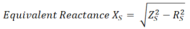
Equivalent circuit parameters (equivalent resistance and reactance) can be calculated from the readings of the Sumpner’s test by the below calculation.

Where RS = Equivalent resistance of transformer referred to the secondary side.
Now, Voltage drop of each transformer:
![]()
Therefore,
Calculation of Temperature Rise
The temperate rise of a transformer can be determined with the help of the Sumpner’s test. Hence, this test is also known as the heat run test. In Sumpner’s test, the temperature of oil and winding after every interval of time. The transformers are operating for a long period (36 to 48 hours) and it results in a temperature rise of oil. From that, the withstand capacity of the transformer is determined under high temperatures.
Advantages & Disadvantages of Sumpner’s Test
Advantage
The advantages of the Sumpner’s test of a transformer are listed below.
- The big capacity of a transformer can be tested without connecting actual load.
- The power required to perform this test is very little. It is equal to the loss of both transformers.
- With the help of the Sumpner’s test, we can find the copper loss, iron loss, temperature rise, equivalent circuit parameters, and efficiency of the transformer.
Disadvantage
The only disadvantage of the Sumpner’s test is that two identical transformers are required to perform this test.
Related Posts:
- Why Transformer Rated In kVA, Not in KW?
- Applications of Transformers
- Parallel Operation of Single-Phase & Three-Phase Transformers
- What is an Ideal Transformer?
- EMF Equation of a Transformer
- Equivalent Circuit of Electrical Transformer
- Transformer Performance & Electrical Parameters
- Power Transformer Protection and Faults
- Transformers Insulation Materials in Oil-Immersed & Dry Type T/F
- Transformers Fire Protection System – Causes, Types & Requirements
- Advantages of Three Phase Transformer over Single Phase Transformer.
- Difference Between Power Transformers and Distribution Transformers?
- Transformer Phasing: The Dot Notation and Dot Convention
- Can We Replace a 110/220 Turns Transformer with 10/20 Turns?
- Electrical Transformer Symbols – Single Line Transformer Symbols
- Can We Operate a 60Hz Transformer on 50Hz Supply Source and Vice Versa?
- Which Transformer is More Efficient When Operates on 50Hz or 60Hz?
- Transformers (MCQs With Explanatory Answers)


