Short Circuit Test and Open Circuit Test of Transformer
Open Circuit (No Load) and Short Circuit (On-Load) Test of a Transformer
As we have seen in the equivalent circuit of transformer, there are four main parameters;
- Equivalent resistance (R01)
- Equivalent reactance (X01)
- Core-loss resistance (R0)
- Magnetizing reactance (X0)
The open circuit and short circuit tests are performed to find circuit parameters, regulation, and efficiency of a transformer. These tests are performed without the actual loading of a transformer. Therefore, these tests are considered as an indirect method of testing.
These tests give more accurate results compared to the test performed on a fully loaded transformer (direct method). Also, these tests are more economical as the power consumption is very less. Two tests considered an indirect method of testing;
- Open-circuit Test
- Short-circuit Test
Related Posts:
- Sumpner’s Test or Back-to-Back Test on a Transformer
- Hopkinson’s Test – Circuit Diagram, Working and Applications
Open Circuit Test (No-Load Test)
The open-circuit test (aka No-load test) is performed to determine the losses in a transformer such as core loss (iron loss), no-load current (I0), and no-load equivalent circuit parameters (R0 and X0). This test is performed either on primary winding or secondary winding. But in most cases, this test is performed on low-voltage winding. Because it is difficult to obtain high voltage in laboratories and the current that passes through the high voltage winding is very small. So, it may be difficult to measure the accurate readings.
Therefore, the open circuit test is performed on low voltage winding. The experimental connection diagram of the open-circuit test on a single-phase transformer is shown in the figure below.
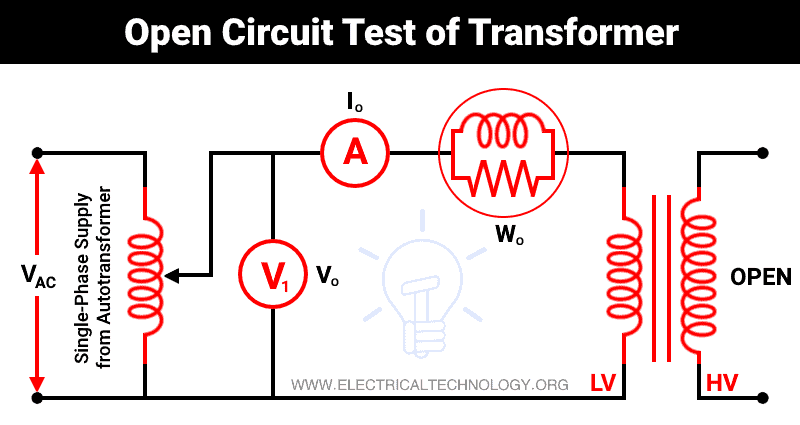
As shown in the above figure, the primary winding (low voltage winding) is supplied by rated voltage and frequency (commonly, a single phase supply from autotransformer). And the secondary winding is kept open. Now, a voltmeter V0, an ammeter I0, and a wattmeter W0 are connected in the primary winding.
The secondary winding is kept open-circuited. Therefore, the current that passes through the secondary winding is zero. And the load is not connected. Hence, the current that passes through the primary winding is no-load current I0. The current that passes through the primary winding is measured by an ammeter that gives the value of no-load current.
The supply voltage given to the primary winding is rated voltage. So, the flux produced in the core of a transformer is normal. And this flux is the same for all loading conditions. The iron loss produced in the transformer depends on the supply voltage and frequency. In this test, we have given rated supply voltage and frequency. Hence, the iron loss or core loss produced in this test is the same for all loads.
The current that passes through the secondary winding is supplied to the iron loss and copper loss in the primary winding. No-load current passes through the primary winding that is very small (2 to 5 percent of full-load current). Therefore, we can neglect the copper loss. And the primary current is supplied for the core loss.
A wattmeter is connected to the primary winding that measures the supplied power. So, the wattmeter indicates the power loss occurred in the transformer core. In an open-circuit test, the reading of instruments is as below;
Ammeter: no-load Current I0
Voltmeter: rated supply voltage V1
Wattmeter: iron or core loss Pi
Observation Table
The observation table of an open circuit test is shown below.
| Rated supply voltage V1 | No-load current I0 | Iron or core loss Pi |
| ….. | ….. | ….. |
Now, we can find the circuit parameter (R0 and X0) using the no-load current.
No-load power W0 = V1 I0 Cos ϕ0 = Iron loss

Working component of no-load current;
IW = I0 Cos ϕ0
Magnetizing component of no-load current;
IM = I0 Sin ϕ0
Now, from the working component and magnetizing component, we can find the no-load resistance and reactance as follows;
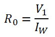
No-load Resistance;
No-load Reactance;

Related Posts:
- Types of Transformers and Their Applications
- Current Transformers (CT) – Types, Characteristic & Applications
- Potential Transformer (PT) – Types & Working of Voltage Transformers
Short Circuit Test (On-Load Test)
The short circuit test (aka On-load test) is performed on the high-voltage side and the low-voltage side is short-circuited. This test could be conducted on the low voltage side, but this test required hardly 5 to 7 percent of rated voltage. On the low voltage side, this voltage is quite small and has chances of a measurement error. Also, reduced voltage (5 to 7 percent) of the high voltage side is easily available in the laboratory. Therefore, it is convenient to perform short circuit tests on the high voltage side.
The schematic diagram of the short circuit test is shown in the figure below.
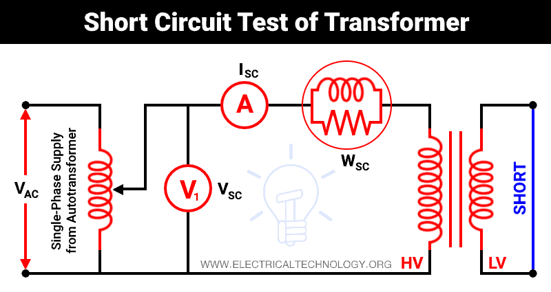
Usually, a low voltage winding is short-circuited using a thick wire. But in some cases, an ammeter is connected to measure the rated load current. An ammeter, a voltmeter, and a wattmeter are connected in the high voltage side as shown in the above figure. Here, we have considered primary winding as high voltage winding and secondary winding as low voltage winding.
The high voltage winding is supplied by the reduced input voltage from a variable supply source. The supply voltage gradually increases until full-load primary current flows through the primary winding. When full-load current passes through the primary winding, by transformer action, the current flows through the secondary winding are full-load secondary current.
So, the ammeter connected in the high voltage side measures the full-load primary current. The voltmeter measures the supplied voltage when full-load current flows through the primary winding. In this condition, the supplied voltage is hardly 5 to 10 percent of full load voltage. Due to low input voltage, the flux produced in the core is very low. And core loss is proportional to the square of flux. Hence, the core loss is very small that can be neglected.
Also, the current that passes through the windings is a full-load current. So, a copper loss that occurs during a test is a normal full-load copper loss. And the wattmeter indicates the full-load copper loss. The secondary winding is short-circuited. So, the secondary voltage (output voltage) is zero. Therefore, the entire primary voltage is used to supply the voltage drop in total impedance referred to as the primary side.
The approximate equivalent circuit of the transformer under the short circuit test is shown in the figure below.

Observation Table:
| VSC Volts | ISC Ampere | PC Watt |
| ….. | ….. | ….. |
The reading of instruments in short-circuit test are as follows;
- Ammeter: Full-load primary current (ISC)
- Voltmeter: Supplied voltage (VSC)
- Wattmeter: Full-load copper loss (PC)
Full-load copper loss;
WSC = I2SC R01
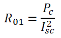
The equivalent resistance of transformer referred to primary;
Equivalent impedance referred to primary;

Equivalent reactance referred to primary;

Power factor;
Related Posts:
- Why Transformer Rated In kVA, Not in KW?
- Parallel Operation of Single-Phase & Three-Phase Transformers
- What is an Ideal Transformer?
- EMF Equation of a Transformer
- Transformer’s Losses – Types of Energy Losses in a Transformer
- Equivalent Circuit of Electrical Transformer
- Transformer Performance & Electrical Parameters
- Power Transformer Protection and Faults
- Transformers Insulation Materials in Oil-Immersed & Dry Type T/F
- Transformers Fire Protection System – Causes, Types & Requirements
- What is the Difference Between Power Transformers and Distribution Transformers?
- Transformer Phasing: The Dot Notation and Dot Convention
- Can We Replace a 110/220 Turns Transformer with 10/20 Turns?
- Electrical Transformer Symbols – Single Line Transformer Symbols
- Can We Operate a 60Hz Transformer on 50Hz Supply Source and Vice Versa?
- Which Transformer is More Efficient When Operates on 50Hz or 60Hz?
- Transformers (MCQs With Explanatory Answers)


