Polarity Test of a Transformer – Circuit Diagram and Working
What is a Polarity Test of a Transformer? Circuit and Working of Additive & Subtractive Polarity Tests
In two winding transformers, one terminal is positive with respect to the other terminal. The polarity of the transformer mentions the relative direction of the induced voltage between the HV and LV windings. In practical transformers, the leads are coming out from the terminals of windings. The polarity of a transformer refers to the way by which the leads are brought out from the transformer.
The polarity of a transformer is important in many aspects. And it is necessary to have the knowledge of polarity while following operations on transformers;
- To connect the instrument transformer (CT and PT) for measuring purposes.
- To connect the protective relays with the transformer.
- To construct a three-phase transformer.
- To connect an extra transformer with an existing transformer in parallel.
In to better understand, always put H1 and H2 or X1 & X1 marking instead of dot marking while finding the polarities of winding terminals. In this case, H1 and H2 marking are used for primary (High Voltage) and H2 for secondary voltage and same is the case for X1 and X2 making.
Related Posts:
- Open Circuit and Short Circuit Test of a Transformer
- Sumpner’s Test or Back-To-Back Test on Transformer
Polarity of Transformer
To mention the polarity in transformer windings, the dot convention (aka dot notation) of a transformer method is used.

In the above figure-A, two dots are shown on the same side of primary and secondary windings. Hence, the current entering the primary side dot is in the same direction as the current leaving the secondary side dot. It means the polarity of the voltages at the dotted ends is in phase. Therefore, if the voltage is positive at a dotted point in the primary winding, the voltage will be positive in the secondary winding also.
As shown in figure-B, two dots are on opposite sides. In this condition, the windings of transformers are wound in opposite directions on the core. Hence, the polarity of the voltages at a dotted point is out of phase. So, if the voltage is positive at a dotted point in the primary winding, the voltage will be negative in the secondary winding.
The polarity of a transformer can be additive or subtractive. To find the additive or subtractive polarity, connect one terminal of primary winding with one terminal of the secondary winding and connect the remaining terminals of primary and secondary winding with a voltmeter.
Additive Polarity
In additive polarity, the voltmeter reads the voltage of summation of primary and secondary voltages. The voltmeter reading is denoted as VC. And the primary and secondary voltage is denoted as VA and VB respectively. In additive polarity, the voltmeter reads;
VC = VA + VB
The circuit diagram of additive polarity is shown in the figure below.

Subtractive Polarity
In subtractive polarity, the voltmeter reads the voltage of subtraction of primary and secondary voltages. The voltmeter reading is denoted by VC and the equation of voltmeter reading is;
VC = VA – VB
The circuit diagram of subtractive polarity is shown in the figure below.

Related Post:
Circuit Diagram of Polarity Test
The circuit diagram of the polarity test is shown in the figure below.
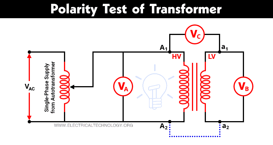
Primary winding terminals are denoted as A1, A2, and secondary winding terminals are denoted as a1, a2. A voltameter VA is connected across the primary winding, a voltameter VB is connected across secondary winding, and a voltmeter VC is connected between primary and secondary winding (between A1 and a1) as shown in the above figure.
An autotransformer is used to get variable supply. A Single-phase AC supply is given to the primary winding. And note down the reading of all voltmeters.
If the reading of voltmeter VC shows the sum of values VA and VB, the connection of the transformer is in additive polarity. And if the reading of voltmeter VC shows the subtraction of values VA and VB, the connection of the transformer is in subtractive polarity.
Polarity Test by DC Source (Battery)
The above method of polarity test is not convenient to determine the relative polarities of terminals of two winding transformers. It can be conveniently carried out by a DC source (battery), a switch, and a DC permanent magnet voltmeter. The connection diagram of this method with proper polarity of battery is shown in the figure below.

A switch is connected in series with the primary winding. As the switch is closed, the battery is connected with the primary winding, and the current passes through the primary winding. It results in the flux linkage in both windings and induces EMF in both windings.
The positive polarity of induced EMF in the primary winding is at the end to which the positive terminal of the battery is connected. If the voltmeter shows positive reading, the polarity is correct. And if the voltmeter moves on the negative side, the polarity is the opposite.
Related Posts:
- Why Transformer Rated In kVA, Not in KW?
- Applications of Transformers
- What is an Ideal Transformer?
- EMF Equation of a Transformer
- Equivalent Circuit of Electrical Transformer
- Transformer’s Losses- Types of Energy Losses in a Transformer
- What is the Transformer’s Voltage Regulation?
- Transformer Efficiency, All day Efficiency & Condition for Maximum Efficiency
- Transformer Performance & Electrical Parameters
- Power Transformer Protection and Faults
- Transformers Fire Protection System – Causes, Types & Requirements
- Advantages of Three Phase Transformer over Single Phase Transformer.
- Difference Between Power Transformers and Distribution Transformers?
- Can We Replace a 110/220 Turns Transformer with 10/20 Turns?
- Electrical Transformer Symbols – Single Line Transformer Symbols
- Can We Operate a 60Hz Transformer on 50Hz Supply Source and Vice Versa?
- Which Transformer is More Efficient When Operates on 50Hz or 60Hz?
- Transformers (MCQs With Explanatory Answers)