What is Crowbar Circuit ? Design and Operation
Crowbar Circuit Diagram for Overvoltage Protection
What is Crowbar Circuit?
The crowbar circuit is basically an electrical circuit used for preventing the circuit from overvoltage condition. It operates by putting a short circuit or low resistance path across the voltage output, very much like dropping a crowbar across the output terminals of the power supply, hence the name. The crowbar circuit is a type of overvoltage protection circuit.
A crowbar circuit is different from other safety or latching circuits for example, a clamp in pulling. Once triggered, the voltage falls below the trigger level, usually close to ground. A crowbar doesn’t return to the normal operation when overvoltage condition is removed.
Based on the operation, an active crowbar is defined as a crowbar that can remove the short circuit when the transient is removed making the device to resume its normal operation. Active crowbars are used when the chances of a transient occurring is high and frequent, in circuits such as rotor circuit of doubly fed generators against high current and voltage transient occurred by the voltage surge in the power network. Thus, the generator can ride through the fault and quickly continue to operate even during the voltage dip.
The crowbar circuit has a low holding voltage that lets it carry higher fault current without losing much power during the process. The lower power loss in crowbar circuit makes it a more preferable option when compared to other safety devices.
- Related Post: 12V to 5V Converter Circuit
Components Required
- Fuse
- Zener Diode
- Schottky Diode
- Thyristors
- Resistors
- Capacitors
Crowbar Circuit Diagram
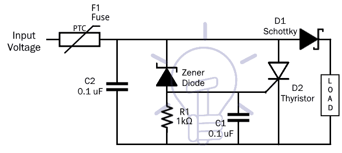
The above circuit diagram is the crowbar circuit which is simple and easy to implement. The circuit is also cost effective and a quick solution for overvoltage protection. The complete crowbar diagram along with the calculated values of the components used.
Fuse
A fuse is an electrical safety device that is used to provide safety to the circuit from overcurrent spikes. Its essential component is a metal wire or strip that is used in series to the circuit. When the current in the circuit is too high, the metal strip melts breaking the circuit. The values of the threshold of the current in a circuit is only depended on the melting point of the metal strip. It is a sacrificial device that means, once it is operated in a circuit to break it, it has to be either replaced or rewired based on the type.
Fuses have been used for a very long time and over time have evolved to work based on very specific current and voltage ratings, breaking capacity and response times, depending on the application.
There are some other devices also available for the same application, called circuit breakers. Circuit breakers can be used as an alternative to the fuses, but they have significantly different characteristics. In general the element of the fuse is of Zinc, copper, aluminium or alloy to get the predictable and stable characteristic.
A general schematic representation of a fuse is given below.

The symbol of the fuse can be different based on different representations. In the above circuit, there are four representations, the first one being IEC representation and the remaining two are based on IEEE representation.
Fuses are widely used because they come with their own set of advantages. Some of them are listed below:
- Fuse is the cheapest device available for protection of an electric circuit.
- Fuse needs zero maintenance.
- Operation of fuse is simple and no complexity is involved.
- Fuse has the ability to interrupt enormous short circuit current without producing noise, flame, gas or smoke.
- The operation time for a fuse can be much smaller than the operation of a circuit breaker.
Of course along with all the advantages, there are also disadvantages though not as many as the advantages. Two of them are given below:
- During short circuit or overload, once fuse blows off replacing of fuse takes time. During this period the circuit loses power.
- When fuses are connected in series it is difficult to discriminate the fuse unless the fuse has significant size difference.
Related Posts:
- Main Difference between Fuse and Circuit Breaker
- HRC Fuse (High Rupturing Capacity Fuse) and its Types
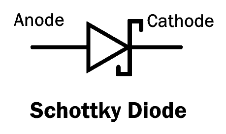
Schottky Diode
Schottky diode in this project is not mandatory and used only for protection purposes. It is mainly used as rectifiers in high frequency low voltage inverters, polarity protection diodes and freewheeling diodes. It is also called as surface barrier diode, hot electron diode or hot carrier diode. It is a little bit different from normal PN junction diodes where metal like platinum or aluminium is used in place of P-type semiconductor.
In Schottky diode, semi-conductor and metal joined, forming a metal semiconductor junction where semiconductor side acts as a cathode and metal side acts as anode. When metal-semiconductor junction formed between metal and semiconductor, they result in depletion layer also referred to as Schottky barrier.
Schottky comes with low stored charge and exhibits lower power loss and higher efficiency mechanical characteristics. It is manufactured in such a way that all external surfaces are corrosion resistant and terminals are easily solderable where current flows in one direction only and it stops the current flowing in other direction. The power drop which happens in this diode is lower than PN junction diodes. When voltage is applied across the diode terminals, current starts to flow which results in small voltage drop across the terminals. The lower voltage drops results in higher efficiency and higher switching speed.
Zener Diode
Zener diode is a type of diode that allows current to flow through it in both the directions unlike a normal diode which allow current flow only in one direction which is from anode to cathode. This flow of current in the opposite direction happens only when the voltage across the terminals exceed the threshold voltage called the Zener voltage. This Zener voltage is a characteristic of the device, which governs the Zener effect which in turn governs the working of the diode.
Zener diodes have highly doped p-n junction, which allows the device to function properly even when there is reverse voltage applied through it. However, many Zener diodes rely instead on avalanche breakdown. Both breakdown types occur in the device, the only difference being, Zener effect is predominant in lower voltages whereas, the avalanche breakdown happens at higher voltages. They are used to generate low-power stabilized power supplies. They are also used to protect circuits from overvoltage, and electrostatic discharge.
- Related Post: Zener Diode & Zener Voltage Regulator Calculator
A schematic diagram of a Zener diode generally used in circuits is given below.
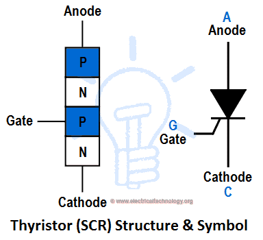
Thyristor
Thyristor is basically a four layered device, it consists for two P-type and two N-type semiconductor alternatively. The constitution of a Thyristor can be shown as P-N-P-N. In its most basic form, a Thyristor has three terminals: anode, cathode and gate. The gate controls the flow of current between anode and cathode. The primary function of Thyristor is to control electric power and current by acting as a switch.
It is mainly used as a rectifier because it can switch rapidly from a state of conducting current to a non-conducting state. In addition, its cost of maintenance is low and operating under the right conditions, remains function in the long term without developing a fault. Thyristors are used extensively and in a wide range of electric circuits, from simpler burglar alarms to power transmission lines.
Working of a Thyristor has been studied extensively over the years and data about its working which is fairly accurate is known. For the most basic type of Thyristor which has four layers (P-N-P-N) and three junctions(PN, NP, PN). If the anode is a positive terminal with respect to the cathode, the junctions PN and PN are forward biased, whereas the centre NP junction is reverse biased. Therefore, the NP junction blocks the flow of positive current from the anode to cathode. The Thyristor is said to be in forward blocking state. Similarly, the flow of negative current is blocked by the outer PN junctions. The Thyristor is in a reverse blocking state. Another state a Thyristor can exist is in the forward conducting state. In this state, it receives a sufficient signal to switch ON, and it starts conducting.
- Related Post: Automatic Doorbell with Object Detection By Arduino
A typical Thyristor diagram is shown in the above figure.
Working of Crowbar Circuit
Attach all the components of the current values as given in the circuit properly. A crowbar circuit keeps the track of the input voltage and it only acts when it exceeds the limit. When the limit is exceeded, the circuit causes a short circuit across the power lines and the fuse connected made of a low melting point metal, melts breaking the circuit. The value of voltage at which the short circuit happen is depend upon the Zener Voltage. The SCR in the circuit is directly connected across the input voltage and the ground of the circuit. However, this SCR is kept turn off by grounding the gate terminal of the SCR. When the Zener voltage is exceeded, the Zener diode starts conducting and the voltage is applied to the gate terminal of the SCR. The voltage applied at the gate terminal of the SCR makes it conduct and there is short circuit between the input voltage and the ground. This short circuit draws the maximum possible current from the circuit and blows up the fuse isolating the power supply from the load.
This arrange of the circuit saves the components and the circuit itself form overshoot of voltages, by blowing up a sacrificial fuse which can be replaced very easily.
Related Posts:


