Losses in Synchronous Motor – Power Stages & Efficiency of Synchronous Motors
Losses, Power Stages and Efficiency of a Synchronous Motor
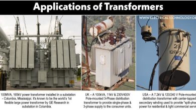
A synchronous motor and an alternator (or synchronous generator) is the same machine except with having the different power flow stages. When the machine is operated to obtain the AC output power (by converting the input mechanical power into output electrical power), it is known to be an alternator or synchronous generator. When the same machine is used to obtain mechanical power ( by converting the input electrical energy into output mechanical energy), it is known to be a synchronous motor. Same is the case for losses in these machine i.e. the losses in synchronous motor and synchronous generator (alternator) is almost same expect the power flow stages.
Related Posts:
- Synchronous Motor: Construction, Working, Types & Applications
- Difference between Synchronous and Asynchronous Motor
Losses in Synchronous Motor
The output mechanical power of a motor is always less than the input electrical power. The energy is wasted in various parts of the machine in the form of heat. It reduces the efficiency of the motor.
The losses in the synchronous motor can be classified into the following categories
- Copper Losses
- Iron and Core Losses
- Rotational and Frictional Losses
Copper Losses
The copper losses (also known as electrical losses) are the losses that occur in the copper windings due to the current and winding resistance. That is why it is also known as I2R losses. If occurs in both stator and rotor of synchronous motor.
Stator Loss: It occurs due to the input AC current and stator winding resistance in the form of heat. It is given by
Pstator = (Istator)2 (Rstator)
Where
- Pstator = power loss in stator
- Istator = input stator current (armature winding)
- Rstator = resistance of stator (armature winding)
Rotor Loss: the rotor loss is relatively smaller than stator loss due to the small DC rotor current flowing through the field winding. It is given by
Protor = (Irotor)2 (Rrotor)
Where
- Protor = Power loss in rotor
- Irotor = DC rotor current (field winding)
- Rrotor = Resistance of rotor (field winding)
Brushes Loss: Similarly the brushes loss is also considered copper I2R losses that account for rotor losses given by
Pbrush_loss = (Irotor)2 (Rbrush)
Related Posts:
- Losses in a DC Motor – Power Stages & Efficiency of DC Motor
- Losses in a DC Generator – Power Stages & Efficiency of DC Generator
Iron and Core Losses
Magnetic Losses
The core losses or iron losses (also known as magnetic losses) are losses that occur in the core or the iron parts of the synchronous motor due to the magnetic property of the material. These losses are classified into two types
- Hysteresis Loss
- Eddy Current Loss
Magnetic Losses = Phys + Peddy
Hysteresis Loss: it occurs due to the magnetization and demagnetization of the ferromagnetic core due to changing magnetic field. A ferromagnetic material does not have the ability to suddenly change its magnetization. During a magnetic reversal, it gradually demagnetizes whereas the applied magnetic field reverses rapidly. A chunk of applied power is used in the demagnetization of the core. This is known as hysteresis loss given by
Phys = ηBmax1.6 fV
Where
- Phys = Hysteresis losses
- η = Hysteresis coefficient
- Bmax = Maximum flux density
- f = Supply frequency
- V = Volume of the magnetic material
Eddy Current Loss: Eddy current loss occurs due to the current induced in the core of the synchronous motor. As we know, a varying magnetic field induces a current in a conductor and the core is made of iron which is a good conductor. The induced current is called Eddy current that circulates in the core, thus wasting the power in the form of heat known as Eddy current loss. It is given by
Peddy = ke B2 f2t2V
Where
- Peddy = Eddy current losses
- Ke = Eddy current coefficient
- Bmax = Maximum flux density
- f = Supply frequency
- t = Thickness of lamination
- V = Volume of the magnetic material
The Eddy current loss is reduced by laminating the core. The core is designed of thin sheets with lamination between them to reduce the induced (Eddy) current.
Related Posts:
- Losses in a induction Motor – Power Stages in Induction Motors
- Losses in Alternator – Power Stages & Efficiency of Synchronous Generator
Rotational and Frictional Losses
Mechanical Losses
The rotation and friction losses (also known as mechanical losses) occur between the stationary and moving parts of the machine. These are constant losses as the rotor speed is constant in a synchronous motor. There are two types of mechanical losses in a synchronous motor.
Friction Losses: In a synchronous motor, friction losses occur in the bearings due to the friction between the rotating part and stationary body. It is given by
Pfriction = k N
Where ‘k’ is constant and ‘N’ is the speed in RPM
Windage Losses: the windage losses occur due to the friction between the rotating parts and air. It is given by
Pwindage = k N3
Windage losses increase with the cube of speed and also depend on the design of the rotor. A salient pole rotor has higher windage losses due to its protruding poles. Therefore speed is taken into account while designing the rotor.
Stray Losses
The difference between the total loss and actual loss is known as stray losses. These are the miscellaneous small losses that occur in a synchronous motor due to various reasons but they cannot be easily accounted for such as flux distortion, non-uniform current distribution in the armature, etc. It is taken as 1% or 0.01 of the total losses.
P stray = 1% P total _losses = 0.01 x P total_losses
Related Posts:
- Losses in Electrical Machines – Formulas and Equations
- Transformer Losses – Different Types of Losses in a Transformer
Power Equations and Power Flow Diagram for Synchronous Motor
There are different power stages in a synchronous motor where the power at each stage decreases due to the losses as shown in the diagram.
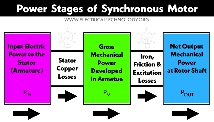
Input electrical power Pin is supplied to the synchronous motor, the output mechanical power Pout is the actual power delivered by the synchronous motor. The electrical and mechanical losses waste the power and reduce the actual power delivered by the motor.

Let’s look into the phasor diagram to understand it better. The phasor diagram for synchronous motor is given below.

Where
- V = Supply voltage per phase
- Ia = Armature current per phase
- Ra = Armature resistance per phase
- Eb = back emf
- Er = resultant voltage, V – Eb
- Zs = synchronous impedance
- θ = internal angle , between Ia and Er
- α = Load angle
- φ = Power factor angle
Input Electrical Power
The input power per phase is given by
Pph = VIa cosφ
The total 3-phase input power to a star-connected synchronous motor is given by
Pin = √3 VL IL Cos φ
Pin = 3 Vph Iph Cos φ
Where
- VL = Line Voltage
- IL = Line Current
- Vph = Phase Voltage
- Iph = Phase Current
Gross Mechanical Power Developed
The gross mechanical power Pm is the power generated in the rotor. It is calculated by subtracting the stator’s windings loss from the input power as given below.
Pstator = 3 Ia2 Ra
Where ‘Ia’ and ‘Ra’ is the armature current and resistance.
Pm = Pin – Pstator
Pm = √3 ILVL Cos φ – 3 Ia2Ra
Or
Pm = back emf x armature current x cosine of the angle between them
Pm = EbIa cos(α − φ) for lagging p.f
Pm = EbIa cos(α + φ) for leading p.f
Output Mechanical Power
The output power is the actual mechanical power delivered to the shaft and eventually to the load. It is calculated by subtracting the magnetic, mechanical and stray losses from the mechanical power such as
Pout = Pm – Pmagnetic -PMechanical
Related Post:
- What is Motor Efficiency and How to improve it?
- Transformer Efficiency, All day Efficiency & Condition for Maximum Efficiency
Efficiency of Synchronous Motor
The efficiency of a synchronous motor is the ratio of output mechanical power Pout to the input electrical power Pin. It is given by
Efficiency, η = Pout / Pin
Efficiency, η = (Pin – Plosses) / Pin
% Efficiency, η = (Pin – Plosses) / Pin x 100%
The efficiency of a synchronous motor depends on losses. As speed is constant, so are the magnetic losses. Therefore the efficiency depends on the connected load. A synchronous motor can have a maximum efficiency of around 90% making it the most efficient motor.
Related Posts:
- Single-Phase Induction Motor – Construction, Working, Types & Applications
- Three-Phase Induction Motor – Construction, Working, Types & Applications
- Alternator or Synchronous Generator: Construction, Working, Types & Applications
- EMF Equation of an Alternator and Synchronous Generator
- EMF Equation of a Transformer
- Power, Voltage and EMF Equation of a DC Motor
- Torque Equation of Induction Motor
- Equivalent Circuit of Induction Motor
- Equivalent Circuit of Electrical Transformer
- Synchronous, Stepper and AC Motors Formulas and Equations