Automatic Reverse Forward Motor Control Using S7-1200 PLC
Control Scheme for Automatic FWD/REV Direction of Rotation of 3-Phase Motor Using Siemens PLC – S7-1200
Industrial automation has become an integral part of manufacturing processes. The use of Programmable Logic Controllers (PLCs) in industry has brought about a significant improvement in process efficiency, productivity and reliability. Automatic reverse-forward motor control is one of the most common applications of PLCs in industrial automation. This article will discuss the automatic forward-reverse motor control using Siemens S7-1200 PLC.
PLC Overview
The S7-1200 is a compact programmable logic controller (PLC) designed for control tasks that require a small to medium amount of I/O points. It is used in various automation applications, such as process control, machine control, building automation and renewable energy applications. The S7-1200 is a powerful and flexible controller that offers a range of features, such as built-in communication protocols, integrated input/output modules, and advanced programming tools.
Motor Control
The automatic REV-FWD motor control is a technique that is commonly used in industrial automation. The motor control system consists of a motor, a three phase power supply, contactors, relay and a controller (like PLC). The controller is responsible for starting and stopping the motor, as well as controlling its direction of rotation. In a reverse-forward motor control system, the motor can rotate in both forward and reverse directions.
Related Posts:
Reverse Forward Motor Control Circuit Using Mitsubishi FX Series PLC
Schematic, Control, Ladder & Wiring Diagrams
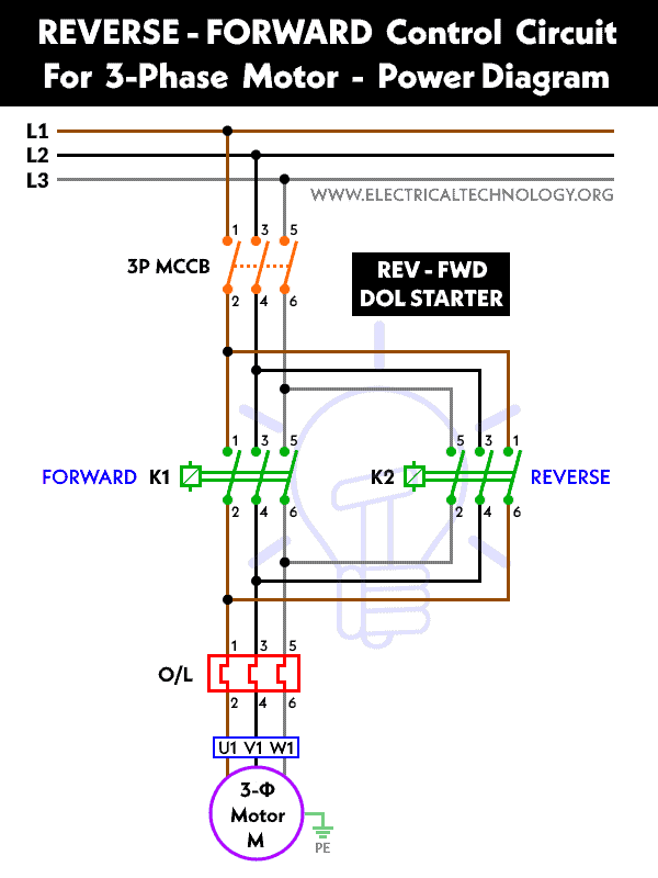
We have used two contactors (K1 for Forward and K2 for Reverse directions) with a thermal overload relay. a three poles MCCB via L1, L2 & L3 for contactors, a two poles MCB for control circuit to use it with thermal overload relay (95 & 96) Start, Forward and Reverse buttons connected to the input terminal of PLC. The output terminals of PLC are connoted to the A1 terminals of both contactors.
Wiring Diagram
The wiring diagram for the automatic changing the direction of rotation of a three phase motor using S7-1200 is shown below:
Click image to enlarge

Power Diagram
PLC Ladder Diagram

Related Posts:
- Star – Delta Starter Motor Control Circuit Using S7-1200 PLC
- Automatic Star – Delta Starter Motor Control Circuit Using LOGO! V8 PLC
Here is how the ladder diagram shows the working of automatic reverse and forward operation of a motor?
Forward Operation:
When the pushbutton for the forward operation is pressed, PIN I0.1 is turned ON, which in turn activates the Q0.0. Since the NO (normally open) contacts are in parallel with I0.1, they remain closed even after the pushbutton is released. This leads to the motor running in the forward direction (i.e., clockwise direction). This is because the Q0.0 and COM pins are activated, which energizes the KM1 contactor used for the forward direction.
Reverse Operation:
When the pushbutton for the reverse operation is pressed, PIN I0.2 is turned ON, and the PLC activates the PIN Q0.1. The main contacts of KM2, used for the reverse direction, close and energize the contactor. This results in the motor rotating in the reverse direction.
PLC Programming
The S7-1200 PLC uses the TIA Portal programming environment, which allows for the development of complex control programs using ladder logic or other programming languages. The ladder logic programming language is the most common language used in PLC programming.
The ladder logic program for the automatic reverse-forward motor control using the S7-1200 PLC consists of two parts: the main program and the subroutines. The main program is responsible for the overall control of the motor, while the subroutines perform specific tasks, such as controlling the direction of rotation of the motor.
Related Posts:
- Star – Delta Motor Control Circuit Using Omron PLC ZEN Programming Relay
- Star – Delta Motor Control Circuit Using Delta – DVP 14SS2 Series PLC
Main Program
The main program consists of the following steps:
- Initialize the PLC and the motor.
- Check the status of the start/stop switch.
- If the start switch is pressed, check the direction switch.
- If the direction switch is set to forward, start the motor in the forward direction.
- If the direction switch is set to reverse, start the motor in the reverse direction.
- If the stop switch is pressed, stop the motor.
Subroutines
The subroutines perform specific tasks, such as controlling the direction of rotation of the motor. The subroutines are called by the main program when needed. In the case of automatic reverse-forward motor control, two subroutines are required:
- Forward Subroutine: This subroutine is responsible for starting the motor in the forward direction. It sets the direction control output to the forward position and activates the motor control output.
- Reverse Subroutine: This subroutine is responsible for starting the motor in the reverse direction. It sets the direction control output to the reverse position and activates the motor control output.
REV-FWD Control Scheme for Changing the Direction of Motor using PLC – S7-1200
To control the automatics reversing direction of rotation of a motor using Siemens S7-200, S7-1500 or S7-1200 PLC, you can follow the following control scheme:
- Start by connecting the input devices (e.g., push buttons or sensors) to the digital inputs of the PLC.
- Connect the output devices (e.g., motor contactors) to the digital outputs of the PLC.
- Write a ladder logic program in the programming software of the PLC to control the motor’s direction of rotation.
- Use a memory bit to store the current direction of rotation of the motor.
- Use a second memory bit to indicate whether the motor is running or not.
- When the start button is pressed, the PLC checks the status of the memory bit that indicates the current direction of rotation of the motor.
- If the bit indicates that the motor is rotating in the forward direction, the PLC turns off the forward contactor and turns on the reverse contactor to change the direction of rotation.
- The PLC then sets the memory bit indicating the current direction of rotation to the reverse direction and sets the memory bit indicating that the motor is running to on.
- When the stop button is pressed, the PLC turns off the forward and reverse contactors and sets the memory bit indicating that the motor is running to off.
- If the start button is pressed again, the PLC checks the status of the memory bit indicating the current direction of rotation and repeats the process to change the direction of rotation if necessary.
This control scheme can be modified to suit the specific needs of your application, and the ladder logic program can be expanded to include additional functionality as required.
Summary
The use of PLCs in industrial automation has brought about significant improvements in process efficiency, productivity and reliability. The automatic reverse-forward motor control is one of the most common applications of PLCs in industrial automation. The Siemens S7-1200 PLC is a powerful and flexible controller that is capable of controlling various industrial automation applications. The automatic reverse-forward motor control using the S7-1200 PLC is a simple yet effective technique that can be used in various industrial automation applications.
Related Power & Control Wiring Diagrams for Motors
- Reverse / Forward Circuit for 3-Phase Motors – Power & Control Diagrams
- Reverse/Forward Circuit for Motors using Start Delta & Timer – Power & Control Diagrams
- Star/Delta Starter Using a Programmable Logic Controller (PLC) – Ladder & Wiring Diagrams.
- Automatic Star-Delta Starter using Timer – Power, Control & Wiring Diagrams
- STAR/DELTA Starter Without Timer – Power, Control & Wiring Diagrams
- Automatic Sequential Operations of Motors – Power, Control, PLC & Wiring Circuits
- Three Phase Slip Ring Rotor Starter – Control & Power Diagrams
- Starting & Stopping of 3-Phase Motor from More than One Place – Power & Control Diagrams
- ON / OFF Three-Phase Motor Circuit – Schematic Power, Control & Wiring Diagrams
- Controlling of 3-Phase Motor from More than Two Places – Power & Control Diagrams
- Multispeed (2 Speeds, 2 Directions) 3-Phase Motor Power & Control Diagrams
- Multispeed (2 Speeds, 1 Direction) 3-Phase Motor Power & Control Diagrams
- Multispeed (3 Speeds, 1 Direction) 3-Phase Motor – Power & Control Diagrams


// Program Name: Reverse Forward Motor Control Circuit
// PLC Model: Mitsubishi FX Series PLC
// Inputs
X0: Start button
X1: Stop button
X2: Reverse button
X3: Forward button
// Outputs
Y0: Reverse contactor coil
Y1: Forward contactor coil
// Latch bits
M0: Forward latched
M1: Reverse latched
// Program
LD X0 // Check start button
OUT Y0 // Energize reverse contactor coil
SET M1 // Latch reverse contactor
LD X2 // Check reverse button
RST M0 // Reset forward latched
OUT Y1 // De-energize forward contactor coil
LD X1 // Check stop button
LD M0 // Check forward latched
OR M1 // Check reverse latched
OUT Y0 // De-energize reverse contactor coil
RST M1 // Reset reverse latched
JP P // Loop