Reverse Forward Motor Control Circuit Using Mitsubishi FX Series PLC
How to Run a Motor in FWD/REV Direction Using Mitsubishi PLC – FX2N and FX5U Series?
Reverse-Forward motor control is a widely used application in industrial automation. The Mitsubishi PLC FX series (e.g. FX2N and FX5U etc.) are popular controllers for motor control applications. In this article, we will discuss the reverse-forward motor control circuit using the Mitsubishi PLC FX2N and FX5U (16ER, 32ER and 32M etc.).
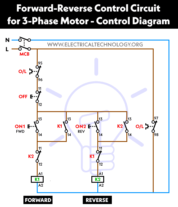
Reverse-Forward Motor Control Circuit:
The reverse-forward motor control circuit is used to control the direction of rotation of a motor. The circuit consists of a three-phase motor, a contactor, and an overload relay. The contactor is used to switch the motor on and off, while the overload relay is used to protect the motor from overload conditions.
The circuit uses two contactors, one for the forward direction and the other for the reverse direction. When the forward contactor is energized, the motor rotates in the forward direction, and when the reverse contactor is energized, the motor rotates in the reverse direction. The overload relay is used to protect the motor from overload conditions.
Hardware & Components Required
- 3-Phase Induction Motor
- 3P MCCB
- 2P MCB
- 3 Nos of NC Push Buttons Switches
- 2 Nos of Magnetic Contactors
- Thermal Overload Relay with NC Auxiliary Relay built-in 24V DC Coil
- Controller like Mitsubishi PLC FX Series (FX2N-16MR-ES, FX2N-32ER, FX5U-32M etc.)
- 400-480V Three Phase supply
- 230V Single Phase Supply
- 24V DC Supply
Following are the Wiring Diagrams for Forward Reverse Motor Operation – Power, Ladder and Control Circuit Using Mitsubishi PLC (Programmable Logic Control).
Related Posts:
- Reverse Forward Motor Control Circuit Using PLC – ZEN Programming Relay
- Star – Delta Motor Control Circuit Using Omron PLC ZEN Programming Relay
Schematic Diagram

Wiring & Power Diagrams
Click image to enlarge

The power circuit diagram shown on the right side in the figure below illustrates a basic reverse forward motor control circuit. The two contactors, KM1 (FWD) and KM2 (REV), are wired to control the changing direction of the motor’s rotation. The forward contactor, KM1, is directly wired to the three-phase supply lines (L1, L2 & L3). On the other hand, the reverse contactor, KM2, is wired in a way where two of the phase lines are interchanged, which is necessary for changing the direction of rotation of the motor.

Instead of the traditional switching operation of contactors via physical wired components like relays and logic switches, the control circuit is contained within the memory of the PLC. Only the push button switches, thermal overload contact, and auxiliary relays are externally connected to the PLC.
The push button switches (for Forward, Reverse, and Stop) are connected to the input terminals of the PLC (Upper portion) while the auxiliary relay is connected to the output terminals (Lower portion).
The rest of the operation is controlled by the internal memory of the PLC using ladder logic, which initiates the activation of the relay and energizes the desired contactor for a specific operation (left, right, clockwise, and anticlockwise direction).
Related Posts:
- Star – Delta Starter Motor Control Circuit Using S7-1200 PLC
- Automatic Star – Delta Starter Motor Control Circuit Using LOGO! V8 PLC
Control Diagram
Ladder Diagram

The ladder diagram for the forward-reverse motor control circuit is shown in the figure below. The internal program within the PLC memory performs all sequential switching functions of the control circuit, which is easily accomplished by constructing the logic sequence wiring diagram using the ladder programming editor of the Mitsubishi PLC software (Such as “GX Works3” GX Developer Software).
Related Posts:
- Star Delta Motor Control Using Schneider Zelio Logic PLC Smart Relay
- Star – Delta Motor Control Circuit Using Delta – DVP 14SS2 Series PLC
Here’s how the ladder diagram shows the working of automatic reverse and forward operation of a motor:
Motor Rotation in Forward Direction:
When the push button for the forward operation is pressed, PIN X0 is turned ON, which activates Y0. Since the NO (normally open) contacts are in parallel with X0, they remain closed even after the push button is released. This leads to the motor running in the forward direction (i.e., clockwise direction). So, when the output of Y0 and COM is activated, they energize the FWD contactor KM1, which leads to running the motor in the forward direction.
Motor Rotation in Reverse Direction:
When the push button for the reverse operation is pressed, PIN X2 is turned ON, and the PLC activates the output PIN Y2. The main contacts of the FWD contactor KM2 close and energize the contactor. This results in the motor rotating in the reverse direction.
PLC Programming:
To implement the reverse-forward motor control circuit using the Mitsubishi PLC (such as the latest controller module FX5U or older versions FX2N etc), we need to write a program that controls the contactors based on the inputs from the operator.
The program should monitor the status of the start and stop buttons and the direction selector switch. When the start button is pressed, the forward contactor should be energized, and the motor should rotate in the forward direction. When the stop button is pressed, both the forward and reverse contactors should be de-energized, and the motor should stop.
If the direction selector switch is set to the reverse position and the start button is pressed, the reverse contactor should be energized, and the motor should rotate in the reverse direction. The stop button should still de-energize both the forward and reverse contactors.
Implementation:
To implement the program, we need to use the ladder logic programming language. The following ladder logic diagram shows the implementation of the reverse-forward motor control circuit using the Mitsubishi PLC.
In the above diagram, X0, X1, and X2 are the inputs to the PLC. X1 is the stop button, X0 is the start – forward button, and X2 is the start – reverse direction switch. Y0 and Y2 are the outputs from the PLC. Y0 controls the forward contactor, and Y2 controls the reverse contactor.
When the forward button (X0) is pressed, the PLC energizes the forward contactor (Y0) when the direction selector switch (X0) is in the forward position. If the direction selector switch is in the reverse position (X2), the PLC energizes the reverse contactor (Y2). If the stop button (X1) is pressed, both the forward and reverse contactors are de-energized, and the motor stops.
Related Motor Control & Power Diagrams:
- Automatic Star-Delta Starter using Timer – Power, Control & Wiring Diagrams
- STAR/DELTA Starter Without Timer – Power, Control & Wiring Diagrams
- Reverse/Forward Circuit for Motors using Start Delta & Timer – Power & Control Diagrams
- Starting & Stopping of 3-Phase Motor from More than One Place – Power & Control Diagrams
- Automatic Sequential Operations of Motors – Power, Control, PLC & Wiring Circuits
- ON / OFF Three-Phase Motor Circuit – Schematic Power, Control & Wiring Diagrams
- Controlling of 3-Phase Motor from More than Two Places – Power & Control Diagrams
- Automatic Sequential Motor Control Circuit – Power & Control Diagrams
- Reverse / Forward Circuit for 3-Phase Motors – Power & Control Diagrams
- Three Phase Slip Ring Rotor Starter – Control & Power Diagrams
- Multispeed (2 Speeds, 2 Directions) 3-Phase Motor Power & Control Diagrams
- Multispeed (2 Speeds, 1 Direction) 3-Phase Motor Power & Control Diagrams
- Multispeed (3 Speeds, 1 Direction) 3-Phase Motor – Power & Control Diagrams
- What is Motor Starter? Types of Motor Starters and Motor Starting Methods
- What is Soft Starter? Its Working, Diagram and Applications
- Direct Online Starter – DOL Starter Wiring Diagram for Motors
- What is a Contactor ? Types, Working and Applications
- Why Do We Need to Install a Starter with a Motor?
- Three Phase Motor Power & Control Wiring Diagrams


