Why are Inductive & Capacitive Reactances Measured in Ohms?
Why are both Inductive and Capacitive Reactances Measured in Ohms instead of Farad, Henry or kVAR?
In a DC circuit, there is no concept of inductive or capacitive reactance because a DC supply has no frequency. Therefore, the opposition to current flow in a DC circuit is simply called resistance, which is measured in Ohms (Ω).
R = V / I
In case of AC circuits, there are three types of resistances viz:
- Resistance
- Inductive reactance
- Capacitive reactance
Resistance: (R): Created by resistors which opposes the flow of current in it. It is represented by the symbol “R” in DC circuits and indicated by the symbol “Z” (known as impedance) in AC circuits. It is measured in Ohms (Ω).
R = V / I
Where V is voltage in volts, and I is current in amp.
Inductive Reactance (XL): Created by inductors which opposes changes in current through a magnetic field. In an inductive circuit, XL increases as frequency increases. Similarly, when current decreases, inductance and inductive reactance increases.
XL = 2πfL
Where f is frequency, and L is inductance in Henry).
Capacitive Reactance (XC): Created by capacitors, which opposes changes in voltage by accumulating electrical charge. In a capacitive circuit, XC decreases as frequency increases. Similarly, when current increase, capacitance and capacitive reactance increases.
XC = 1/(2πfC)
Where f is frequency, and C = Capacitance in Farads.
It clearly shows that the resistance of a DC circuit is totally different than the AC circuit. In other words, resistance in AC circuits is known Impedance (Z) which is the overall resistance of the AC circuit caused by resistors, inductors and capacitors.
AC resistance in case of inductive load
Z = √ (R2 + XL2)
AC resistance in case of capacitive load
Z = √ (R2 + XC2)
AC resistance In case of both inductive and capacitive loads.
Z = √ (R2 + (XL– XC)2
Why Reactances Measured in Ohms (Ω)
Although the capacitance of a capacitor is measured in farads (F) and the inductance of an inductor is measured in henries (H), the capacitive reactance and inductive reactance produced by them are measured in ohms (Ω), just like electrical resistance.
Reactances refer to the opposition presented to alternating current (AC) by inductance and capacitance in an electrical circuit. Measured in Ohms (Ω), they store and release energy rather than dissipating it as heat.
Inductive Reactance (XL) caused by inductors and Capacitive Reactance (XC) caused by capacitors are both forms of resistance to alternating current (AC). Because they are oppositions to current flow, they are measured in Ohms (Ω).
However, the reactive power they consume or produce is measured in kVAR (kilo-Volt-Amperes Reactive). Because reactances do not consume real power (Watts), the power they exchange with the grid is defined entirely by their reactive power, kVAR.
In AC systems, total power is composed of three elements
- Active Power (kW): The real, useful work done (e.g., heat or motion)
- Reactive Power (kVAR): The power needed to establish and maintain magnetic and electric fields, oscillating back and forth in the circuit without performing useful work
- Apparent Power (kVA): The total vector sum of kW and kVAR.
Inductive and capacitive reactances have an exactly opposite effect on the circuit’s alternating current (AC):
- Inductors: cause current to lag behind voltage. They draw inductive reactive power (+kVAR) from the system to create magnetic fields (e.g., in motors and transformers).
- Capacitors: cause current to lead voltage. They generate and supply capacitive reactive power (-kVAR) to the system.
Why Use kVAR for Reactive Power Produced by Capacitors and Inductors?
kVAR (kilovolt-amperes reactive) is the unit used to measure Reactive Power (Q), not the reactance itself. This is because reactive power and reactances by capacitors and inductors are totally different quantities.
The power associated with inductors and capacitors is produced in such a way that they store and release energy rather than consume it. Therefore, their power is inherently reactive.
In a power system, reactive power oscillates back and forth between the source and a reactive element without being converted to useful work (heat, light, motion, etc.). The unit applies to any element that causes a 90° phase shift between voltage and current.
In both cases, the average real power (watts) consumed over a full cycle is zero i.e. energy goes in and comes back out. The unit kVAR captures this “back-and-forth” power exchange, regardless of whether the reactive element is a coil or a capacitor.
For any reactive element, reactive power is:
Q = V × I × sin(θ)
- For an inductor: θ = +90°, so sin(90°) = +1 … Q is positive
- For a capacitor: θ = −90°, so sin(−90°) = -1 … Q is negative
Both yield a value in volt-amperes reactive (VAR), just with opposite signs. The unit is the same; the sign distinguishes them.
In power systems, inductive and capacitive reactance are treated as opposing forces:
- Inductors consume reactive power (+kVAR)
- capacitors generate/supply reactive power (-kVAR)
This is why capacitor banks are used for power factor correction i.e. their negative kVAR cancels out the positive kVAR of inductive loads (motors, transformers), reducing the total reactive burden on the grid.
When there are too many motors and transformers (inductive load) in a power system, the voltage drops and efficiency decreases. In this case, engineers installs capacitors to inject “leading” kVAR to cancel out the “lagging” kVAR of the motors (caused by inductive load). This process is called Power Factor Correction.
The kVAR rating of any reactive (non-dissipative) power has the following advantages.
- Direct Offset: Capacitors are deliberately installed to cancel out the inductive reactance in a system. Since one generates positive kVAR and the other consumes positive kVAR, they perfectly cancel each other out.
- System Capacity: Utilities measure both in kVAR to calculate how much unnecessary “magnetizing” current is flowing through the cables, transformers, and generators.
- Device Rating: Capacitors are rated in kVAR to show exactly how much inductive reactive power they can offset (e.g., compensating for motor loads).
Related Posts:
- Why is the Rating of a Capacitor Expressed in Farad?
- Why is a Capacitor Bank Rated in kVAR, Not in Farad?
- Why is a Transformer Rated in kVA, but Not in kW?
- Why is a Motor rated in kW instead of kVA?
- Why is an Alternator and Generator rated in kVA, not in kW?
- Why is a Battery rated in Ah (Ampere hour) and not in VA?
- Why is an Air-condition (AC) Rated in Ton, not kW or kVA?
- Why is a Power Plant Capacity Rated in MW and not in MVA?
- Why was a Circuit Breaker Capacity Rated in MVA and Now in kA and kV?
Resources:
- Why are Capacitors Connected in Series in Power Lines?
- Why is a Capacitor Bank Connected in Parallel and Not in Series for P.F?
- Why is a Capacitor Needed for a Single-Phase Motor?
- How to Find the Value of Fan Capacitor – Motor Capacitor Calculator
- How to Calculate the Suitable Capacitor Size in µ-Farads & kVAR for P.F Improvement
- How to Convert Capacitor μ-Farads to kVAR and Vice Versa? – For P.F Correction
- Power Factor Correction Calculator – How to Find P.F Capacitor in µF & kVAR?
- What Happens if We Connect a Polar Capacitor the Wrong Way?
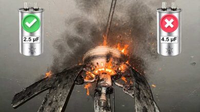
- What Happens If You Install a Larger Capacitor in a Fan?
- What is the Role of Capacitor in a Ceiling Fan?
- What is the Role of Capacitor in AC and DC Circuit?
- Why Does a Capacitor Block DC But Pass AC?
- Difference Between a Battery and a Capacitor
- In a Capacitive Circuit, Why the Current Increases When Frequency Increases?
- In an Inductive Circuit, Why the Current Increases When Frequency Decreases?
- Why Power Factor Decreases When Capacitive Reactance Increases or Capacitance Decreases?
- Why Power Factor Decreases When Inductance or Inductive Reactance Increases?
- Why Current Increases When Capacitance Increases or Capacitive Reactance Decreases?
- Why Current Decreases When Inductance or Inductive Reactance Increases?