24V Flasher Circuit
24V Flasher Circuit Diagram using 555 Timer
Industrial level control devices like PLC, HMI, etc. have an operating voltage of 12V or 24V. The loads (LED indicator) and sensors, that are used to interface with a PLC, also have a nominal operating voltage of 24 V. Other than that, a few automobiles wiring harnesses also operate on 24V. There are also 24V bulbs that are used in taillights or headlights of automobiles. The circuit in discussion “the 24V flasher circuit” is also a circuit used in automobiles for a function that we encounter on a daily basis. The “24V Flasher relay circuit” is used in the indicator lights on our automobiles. This report will explain one of the uses of the flasher circuit that is used in automobile indicators.
Components Required
- 24V bulb
- 7085 Regulator IC
- Relay 5V
- 555 Timer IC
- BC547 Transistor
- Diode 1N4007
- Resistor – 1k, 470k
- Capacitor – 10uf, 0.1uf
- 24V Power supply
24V Flasher Circuit Circuit Diagram
The complete circuit diagram for the 24V bulb flasher relay circuit along with the corrected calculated values is given below.

A bulb flasher circuit is very common circuit which most of us come across from time to time. In automobiles, when the indicator is signalled, along with the blinking there is also a clicking sound which is heard along with the blinking periodically. The sound is due to the relay that is being switched ON and OFF which in turn completes and breaks the circuit making the bulb flash. The ticking circuit will be designed in this project using a 555 timer.
555 Timer IC
555 timer IC is introduces in 1972, it’s basically used for pulse generation, and oscillator application. The pin diagram of the 555 Timer IC is given below.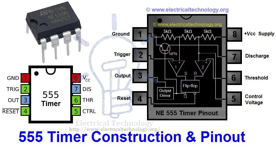
| 555 Timer IC | ||
| Pin no. | Pin Name | Purpose |
| 1 | GND | Ground reference voltage |
| 2 | TRIG | Controls output |
| 3 | OUT | Is driven to ~1.7V below Vcc or to ground |
| 4 | RESET | Reset a timing interval |
| 5 | CTRL | Provides access to the internal voltage divider |
| 6 | THR | Acts as the threshold as to when to stop the timing interval |
| 7 | DIS | Open collector output to discharge capacitor |
| 8 | Vcc | Positive supply voltage |
There are three modes of operation of the Timer IC, which are bistable, monostable and astable mode.
- In bistable mode, the circuit produces 2-stable state signals that are in low and high states. The output signals of low and high states signals are controlled by reset and activating the input pins.
- In monostable mode, the circuit generates only single pulse when the timer gets an indication from input of the trigger button.
- In astable mode, the circuit of the IC produces a continuous pulse with exact frequency based on the value of the two resistors and capacitors which are connected in the external circuit.
Related Post: Clap Switch Circuit Using IC 555 Timer & Without Timer
7805 Regulator IC
Circuits that have voltage sources in them may have fluctuations resulting in not providing a fixed voltage outputs. One of the popular ICs for this purpose is 7805 Regulator IC, which is a member of fixed linear voltage regulators used to maintain such fluctuations. There are many application where 7805 play a very important role:
- Fixed-output regulator
- Positive regulator in negative
- Adjustable output regulator
- Current regulator
- Adjustable DC voltage regulator
- Regulated dual supply
- Output polarity reversal protection circuit
- Reverse bias projection circuit

| LM 7805 voltage regulator IC | ||
| Pin no | Pin name | purpose |
| 1 | Input | Apply an unregulated voltage to get a regulated output |
| 2 | Ground | Connected to ground |
| 3 | Output | Output is a regulated voltage signal |
The IC when given an input voltage of 7.2V, will achieve its maximum efficiency.
In IC 7805 voltage regulator, lots of energy is exhausted in the form of the heat. The difference in the value of the input voltage and the output voltage comes as heat. So, if the difference between the input voltage and the output voltage is high, there will be more heat generation. So, this IC also provides a provision for a heat sink.
BC547 Transistor
BC547 is an NPN bipolar junction transistor. Mostly it is used for the switching purpose as well as for amplification processes. The smaller amount of current at the base is used to control the larger amount of currents at collector and emitter as well. Its basic applications are switching and amplification. Below is the pinout for the BC547 transistor.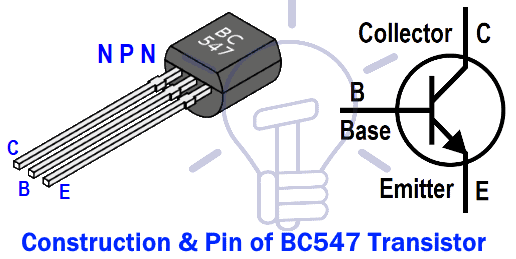
The working of the transistor is straightforward. When the input voltage is applied at its terminals, some amount of current starts to flow from base to the emitter and controls the current at collector. The voltage between the base and the emitter is negative at the emitter and positive at the base terminal for its NPN construction.
- Related Post: IC 555 Timer Calculator with Formulas and Equations
1N4007 Diode
1N4007 is a PN junction rectifier diode. These types of diodes allow only the flow of the electrical current in one direction. So, it can be used for the conversion of AC power to DC. 1N4007 has different real life applications, e.g. free-wheeling diodes applications, general purpose rectification of power supplies, inverters, converters etc. The pinout for the given Diode is given below.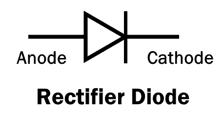
| 1N4007 Diode | ||
| Pin no. | Pin name | Charge |
| 1 | Anode | +ve |
| 2 | cathode | -ve |
The diagram above shows the symbolic picture of the 1N4007. The understanding of any component of an electrical circuit is vastly improved when the electrical characteristics of that device is known. The electrical characteristics of the diode 1N4007 is tabulated below.
| 1N4007 Electrical Characteristics | ||
| Parameter | Values | Units |
| Forward voltage at 1.0 A | 1.1 | V |
| Reverse current at 25°C | 5 | uA |
| Total capacitance at 1.0 MHz | 15 | pF |
| Maximum full load reverse current at 75° | 30 | uA |
| Average rectified forward current | 1 | A |
| Peak repetitive reverse voltage | 1000 | V |
The diode 1N4007 features are as follows:
- Low leakage current
- Low forward voltage drop
- High forward surge capability
This diode ha a lot of real life applications in embedded systems, a few of the major applications associated with the particular diode are given below:
- Converters
- For switching purposes in embedded systems
- Freewheeling diodes applications
- Inverters
- General power rectification of power supplies
- To avoid reverse current and protecting microcontrollers like Arduino or PIC microcontroller.
Related Post: Electronics Engineering Project Ideas for Engineering Students
Relay
A relay is an electrically operated switch. The switch may have any number of contacts in multiple contact forms, such as make contacts, break contacts, or combination of these two. Relays are used to control a circuit by an independent low-power signal, or where several circuits must be controlled by one signal. The old relays have electromagnet for opening and closing the contacts, but now other operating principles have been invented like solid state relay. It basically uses semiconductor properties for controlling without relying on any moving parts. The pinout of a 5V relay which is used in the circuit’s construction is given below.

| 5V Relay | ||
| Pin no | Pin name | Description |
| 1 | Coil end 1 | Used to trigger the relay |
| 2 | Coil end 2 | Used to trigger the relay |
| 3 | Common(COM) | Connected to one end of the load |
| 4 | Normally close (NC) | If the other end is connected to this terminal, the load remains connected before trigger |
| 5 | Normally open(NO) | If the other end is connected to this terminal, the load remains disconnected before the trigger |
Working of 24V Flasher Circuit
Connect the components properly as shown in the circuit diagram given. The positive ends of the bulbs are tied together and connected to the relay. The positive ends of the bulbs are tied together and connected to the 24V supply, in order to switch the bulbs, the negative ends are connected to a relay. The common pin of the relay is connected to the Relay and the normally open (NO) pin is connected to one of the bulb’s negative end and the normally closed (NC) pin of the relay is connected to the other bulbs negative end. This way only one bulb will be turned on at any given time.
The relay needs to be turned ON and OFF periodically. This function will be taken care of by a 555 timer. We use the 555 Timer in a stable mode to produce a pulse with a predefined on and off times. In our circuit, the one of the bulbs will be ON in the ON state and the other will be ON in the OFF state. The voltage supply we have is of 24V, but the 555 timer takes a much lesser operating voltage. So, we use the 7805 voltage regulator which will regulate the input 24V to 5V which can be used to power the timer and relay. The NPN transistor BC547 (or 2N2222) is used to turn ON or OFF the relay according to the pulses given by the timer. But the current output from the 555 timer is not enough to turn ON or OFF the relay, we use a transistor in between through a base resistor. This circuit is called a relay driver circuit. The finished circuit along with all the correct connections and values of the components should give a working 24V flasher circuit.
Related Posts:


Am I in need of new glasses or does the caption for the transistor in the schematic say “2N2222”? Which would make it a PNP, if I’m not mistaken.
The NPN transistor BC547 (or 2N2222) is used to turn on or off the relay using the 555 timer.