Varactor Diode – Symbol, Construction, Working and Applications
What is Varactor Diode? It’s Symbol, Construction, Working, Advantages, Disadvantages and Applications
Diodes are semiconductor-based components that allow current in one direction and block in the other direction. There are several types of diodes used in circuits. Varactor diode is a type of diode that we will discuss in this article in detail.
As the Varactor Diode is more related to the capacitor, let’s have the introduction of a capacitor.
Related Posts:
- What is Diode? Construction and Working of PN Junction Diode
- Types of Diodes and Their Applications – 24 Types of Diodes
Capacitor
A capacitor is a component that store charge between its plates in the form of an electric field. Its ability to store charge is called capacitance. Whereas the capacitance depends on the area of these plates as well as the distance between them.

The conducting plates are separated by an insulating material known as dielectric that blocks the flow of charge between them but the electric lines of force.
As both conducting plates are connected to separate terminals of the battery or source. One of the plates accumulates positive while the other accumulates negative charge. As the charge builds up, there is a field generated between them known as the electric field.
Varactor Diode
A Varactor diode is a PN junction diode whose capacitance varies with the change in applied reverse voltage. The internal capacitance is actually the junction capacitance that depends on the width of the junction. As the width of the depletion region varies with the applied reverse voltage, the capacitance of the varactor diode varies with the applied voltage.
A varactor diode is a voltage-dependent component whose output depends on the input voltage. It is used as a variable capacitor whose capacitance is controlled by adjusting the applied reverse voltage.
Good to know: Varactor diode is also known as Varicap Diode, Tunning Diode, Voltcap Diode and Voltage Variable Capacitance Diode.
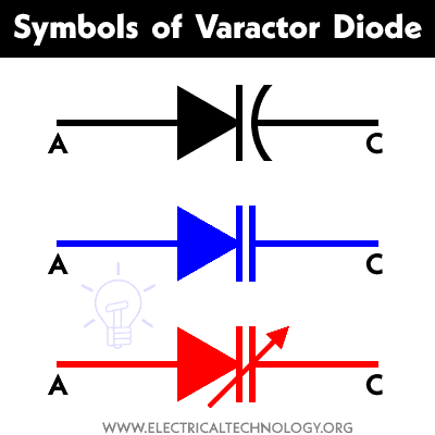
Symbol of Varactor Diode
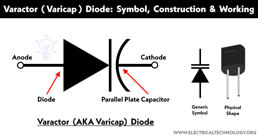
The symbol of a varactor diode resembles both a conventional diode and a capacitor. It has two terminals; anode and cathode. The symbol can be clearly divided into the diode and capacitor parts where the anode is at the diode side and the cathode is at the capacitor side as shown in the figure below.
Related Posts:
- Fast Recovery Diode: Construction, Working and Applications
- Step Recovery Diode – SRD: Construction, Working and Applications
Construction of Varicap Diode
The varactor diode is a PN junction diode made from combining two layers of semiconductor material i.e. P-type semiconductor and N-type semiconductor. When both layers are combined a depletion region is formed in between. The depletion region is free of charge. However, the N-layer and P-layer has the majority of electrons and holes respectively. But the depletion region does not allow the flow of these carriers unless a potential is applied.
The main difference between a conventional PN diode and a varactor diode is that a conventional diode has uniform doping concentration while the doping concentration in the varactor diode is lower near the junction and increases as we go toward the outer terminals.

The P-type semiconductor and N-type semiconductor is constructed on top of a Mesa structure. The semiconductor used is silicon (low frequency) or gallium arsenide(high frequency). Gold-plated molybdenum studs are connected with the N-type layer through the Mesa structure while it is connected with the P-type semiconductor through a gold-plated wire. They are used as terminals; anode and cathode. It is enclosed in a ceramic structure.
Working and Operation
A Varactor diode is designed to have a variable capacitance that varies with the applied reverse voltage. Therefore it is necessary to understand the working of a variable capacitor before. A capacitor has two conducting plates separated by a dielectric medium where one of the plates is connected to the positive and the other is connected to the negative voltage. As the dielectric medium does not allow the flow of charge, the charge accumulates in the surface of the plates known as the capacitance. This capacitance depends on several factors including the gap between the plates. The capacitance is inversely proportional to the gap between the plates. This working principle of the variable capacitor is used in the varactor diode.

A varactor diode is made of a P-type semiconductor layer and N-type semiconductor layer joined together to form a PN junction. The P-type layer has the majority of positive charge while the N-type layer has the majority of negative charge. The charge combined in the middle and neutralizes each other forming a gap between the layers called the depletion region. The structure formed resembles a capacitor whose capacitance depends on the width of the depletion region.

If the varactor diode is connected in forward bias i.e. the anode is connected with positive while the cathode is connected with the negative terminal of the voltage source, the width of the depletion region reduces that eventually disappears allowing a large current through it. Since there is a flow of current, the Varactor diode is not used in forward bias.

If the varactor diode is connected in reverse bias i.e. the anode is connected with the negative and the cathode is connected with the positive terminal of the voltage source. The applied reverse voltage pulls the charge away from the junction increasing the width of the depletion region. As the reverse voltage is increased, the depletion region also increases. Thus we can control the width of the depletion region through the applied voltage.
The given structure is similar to that of a capacitor where the semiconductor layers are the two conducting plates that store charge while the depletion region is the dielectric separation between them. The capacitance of the PN junction is called junction capacitance.
As given in the reverse bias, the charge is stored in the opposite layers. If the depletion width is reduced more charge will be stored i.e. the capacitance will increase. If the depletion width is increased, the charge stored will be reduced and the capacitance will also decrease. Since the depletion width is controlled by varying the applied reverse voltage, we can vary the capacitance of the varactor diode by varying the reverse voltage.
Therefore we can calculate the capacitance of the varactor diode using a variable capacitor formula. The expression for the junction capacitance of the varactor diode is given by
Cj = εA/d
Where
- Cj = Junction capacitance
- ε = permittivity of the semiconductor
- A = cross-sectional area of the junction
- D = width of the depletion region
The Varactor diode is used as a capacitor for storing the charge and not conducting it. As it conducts in forward bias and blocks (stores) charge in reverse bias. Therefore varactor diode is only used in reverse bias and not in forward bias.
Related Posts:
- Schottky Diode: Construction, Working, Advantages and Applications
- Shockley Diode: Construction, Working, Characteristics and Applications
Characteristics of Varactor Diode
The characteristic curve shows the relationship between the capacitance and the reverse bias voltage of the varactor diode. The vertical axis show capacitance and the horizontal axis shows the reverse voltage as shown in the figure below.
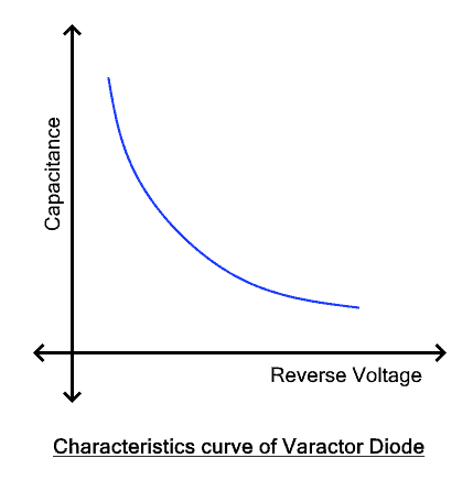
The graph clearly shows that the capacitance decreases with the increase in the reverse voltage. This is due to the increasing junction width with the applied voltage.
The exact value of the capacitance of a varactor diode using the values of the applied voltage can be measured using the given formula.
Cj = CK / (Vb – Vr)m
Where:
- Cj = Junction Capacitance of Varactor diode
- C = Capacitance at the unbiased condition
- K = Constant equal to 1
- Vb = Barrier potential
- Vr = Applied Reverse Voltage
- m = Constant that depends on the semiconductor material and its doping concentration (0.33 – 0.5)
Related Posts:
- Gunn Diode: Symbol, Construction Working and Applications
- Constant Current Diode – Working, Construction, and Applications
Tuning Circuit using Varactor Diode
The varactor diode is used in tuning the circuit to adjust the resonance frequency of the circuit by varying the voltage. The given figure shows a tuning circuit

It is an RLC circuit with two varactor diodes D1 and D2 as variable capacitors C1 and C2 respectively, resistor R and inductor L. The two diodes are connected in reverse bias i.e. their cathodes are connected with a variable positive DC voltage supply. This variable DC voltage is used to vary the capacitance of both diodes. Therefore, the total capacitance Ct is the combined capacitance of both diodes. The resonant frequency of the given tuning circuit is given by
f0 = 1/2π√(LCt)
Where
- Ct = C1 C2 / (C1 + C2)
- F0 = resonant frequency
- L = inductance measured in Henry
- Ct = total equivalent capacitance of both diodes
Advantages & Disadvantages of Varactor Diodes
Advantages
Here are some advantages of varactor diode
- The main advantage of a varactor diode is that its capacitance is easily controlled by varying the applied voltage.
- Its operation is noise-less as compared to other diodes.
- It has lower power losses due to less noise. Thus it is more efficient.
- It has a small size and compact design having small weight.
- It is inexpensive and economical.
- It is more reliable.
Disadvantages
Here are some disadvantages of varactor diode
- The reverse voltage must not increase over the breakdown voltage, otherwise, the diode gets damaged.
Applications
Varactor diode is mainly used as a variable capacitor as its cathode and anode are used as the conducting plates and the depletion region acts as the dielectric medium between them. However, they are used in multiple applications where some of which are given below.
- It is used as a tuning capacitor that replaced the old-style mechanically tuned capacitor in television and radios.
- It is used to design VCO (voltage-controlled oscillator) that is used in transmitting and receiving circuits in communication.
- It is also used as a frequency multiplier.
- It is also used in PLL (phase lock loop) for modulation in communication.
- It is used in small remote control circuits.
- It is used in frequency filters with adjustable bandwidth.
- It is also used in the harmonic generator.
Related Posts:
- LED – Light Emitting Diode: Construction, Working, Types and Applications
- Photodiode: Types, Construction, Operation, Modes, Performance and Applications
- Backward Diode: Construction, Operation, Characteristics and Applications
- What is a Laser Diode? Construction, Working, Types and Applications
- What is Avalanche Diode? Construction, Working, Types and Applications
- Tunnel Diode: Construction, Working, Advantages, and Applications
- Zener Diode – Symbol, Construction, Circuit, Working and Applications
- Blocking Diode and Bypass Diodes in a Solar Panel Junction Box
- Diode Formulas and Equations – Zenner, Shockley and Rectifier
- Diode Symbols – Electronic and Electrical Symbols
- Applications of Diodes


