Diode Formulas & Equations – Zenner, Shockley & Rectifier
Shockley, Zenner & Diode Rectifier Formulas and Equations
Diode Equation for I-V Curve
The I-V curve (diode characteristic curve) can be find by the following no linear equations. This equation is also known as Ideal Equation of Diode or Diode Law.
i = IS ( eqv/kT – 1 )
Where:
- i = Current flowing through the diode
- Is = Reverse or dark saturation current (Typical value for silicon is 10-12 Amperes)
- e = Base of the neutral logarithm (2.71828)
- q = Charge on electron (1.602 x 10⁻¹⁹) in coulombs (Absolute Value of electron charge).
- v = Applied voltage across the diode
- k = Boltzmann’s constant (1.380 x 10⁻²³ jouals/Kelvin)
- T = Absolute Temperature in Kelvin (Typical Room Temp is 300 Kelvin)

Shockley Diode Equation:
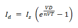
Where
- ID = current through the diode
- VD = diode voltage
- Is = leakage or reverse saturation current
- n = emission coefficient or ideality factor, for germanium n=1, for silicon it ranges in 1.1-1.8.
- VT = thermal voltage which is

Where
- q = charge of electron = 1.6022 x 10⁻¹⁹ coulomb
- T = absolute temperature in Kelvin (K = 273 + °C)
- k = Boltzmann’s constant = 1.3806 x 10²³ J/K
Zenner Diode Formulas & Equations
You may check the Zener diode based regulator calculator in the previous post.
Series Current
IS = VIN – VZ/RS ….. (Ohm’s Law)
Zener Current
IZ = IS – IL
Load Current
IL = VL/RL
Load Voltage
VL = VZ
Change in Load Voltage
∆VL = IZ RZ
Output (Regulated) Voltage
- VOut = VIN – I R
- VOut = VIN – (IZ + IL)/RS
- VOut = (VIN – IS)/RS
Series Resistance
RS = (VL – Vout) / (IZ + IL) = (VL – Vout)/(IS)
Max Series Resistance
RS (MAX) = RL (MIN) x [(VIN (MIN) / VZ) -1]
RS (MAX) = RL (MIN) x [(VIN (MIN) – VZ)/IL(MAX)]
Value of Resistor
R = [(VIN (MIN) – VOUT)/(IL + 10)]
Power of Resistor
RP = (VIN (Max) – Vout) 2 / R
Power of Zener Diode
ZP = (VIN(MIN) – VOUT) / R) x VOUT
Output Ripple
VR (OUT) ≈ VR (IN) x (RZ/RS)
Diode Rectifier Equations:
A rectifier’s output contains DC as well as AC components, So;
Output DC Power:
Pdc = Vdc Idc
Where
- Vdc is the average output voltage
- Idc is the average output current
Output AC Power:
Pac = Vrms Irms
Where
- Vrms Is the rms of output voltage
- Irms is the rms of output current
Rectifier Efficiency:
The efficiency of the rectifier denote by η is given by:

Where
- Pdc is the output DC power
- Pac is the output AC power
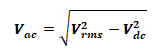
Output AC Voltage:
The rms of AC component of the output voltage is:
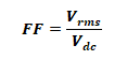
Form Factor:
The ratio of RMS voltage to the average dc voltage,
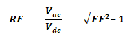
Ripple Factor:
It’s the ratio between the AC and DC component of the rectifier. It shows the purity of the DC output.
Related Formulas and Equations Posts:
- Basic Electrical Engineering Formulas and Equations
- Resistance, Conductance, Impedance and Admittance Formulas
- Resistance, Capacitance & Inductance in Series-Parallel – Equation & Formulas
- Equations & Formulas For RLC Circuits (Series & Parallel)
- Basic Electrical Quantities Formulas
- Power Formulas in DC and AC Single-Phase & Three-Phase Circuits
- Magnetic Terms used in Magnetic Circuits – Definition & Formulas
- Formula and Equations For Inductor and Inductance
- Formula and Equations For Capacitor and Capacitance
- Electric & Magnetic Flux, Density & Field Intensity Formulas
- Formula & Equations for Ohm’s, Kirchhoff’s & Coulomb’s Laws
- Voltage & Current Divider Rules (VDR & CDR) Equations
- Losses in Electrical Machines – Formulas and Equations
- DC Generator Formulas and Equations
- Power, Voltage and EMF Equation of a DC Motor – Formulas
- Synchronous Generator and Alternator Formulas & Equations
- Synchronous, Stepper and AC Motors Formulas and Equations
- Induction Motor & Linear Induction Motors Formulas & Equations
- Transformer Formulas and Equations
- Electrical & Electronics Engineering Formulas & Equations
- Electrical & Electronics Elements & Symbols