How to Reverse and Forward a Three-Phase Motor Using a VFD?
How to Change the Direction of Motor Rotation Using a VFD?
Variable Frequency Drives (VFDs) have revolutionized industrial automation by providing precise control over the speed and direction of electric motors. Among their many applications, one of the most common uses of VFDs is to reverse and forward three-phase motors. This tutorial will guide you on how to control the direction of a three-phase motor (reversal and forward operation) using a VFD with the help of power, wiring, and control diagrams for both PNP and NPN modes.
What are VFDs?
A Variable Frequency Drive (VFD) is an electronic device used to control the speed of AC motors by varying the frequency and voltage supplied to the motor. VFDs convert the incoming AC power into a DC voltage, and then convert it back to AC at the desired frequency and voltage. This technology enables precise speed control, energy savings, and improved motor performance.
- Related Post: How to Wire a VFD with Motor?
Components Required
- 3-P MCCB
- Three-Phase Motor
- Variable Frequency Drive (VFD)
- Three Phase Supply
- 2 Nos. of ON/OFF switches for manual REV/FWD Operation
- Wires & Cables
- Programmable logic controller (PLC) for controlling the VFD’s operation (Optional)
Wiring the Three-Phase Motor and VFD
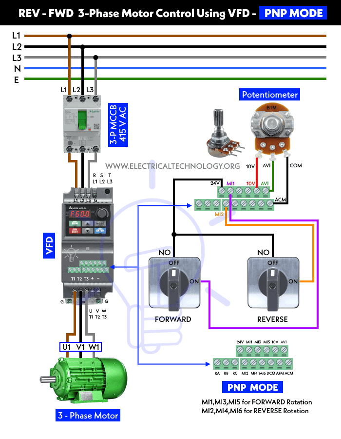
Power Wiring: Connect the 415V AC three-phase power supply from the 3-P MCCB to the VFD’s L1, L2, and L3 terminals. Now connect the three-phase motor to the VFD’s output terminals of T1, T2 and T3. Make sure the correct phases are matched and in sequence. If not sure, follow the manufacturer’s guidelines for proper wire sizing and connections.
Control Wiring: Connect control devices to the VFD’s control inputs. Commonly used control methods include a forward button, a reverse button, and a stop button. These buttons can be wired to digital inputs on the VFD or a connected PLC. To do so, follow the following steps
For PNP Mode:
- Connect a wire from the 24V terminal of the VFD to the NO (normally open) terminal of both the Forward and Reverse switches.
- Connect the MI1 terminal of the VFD to the second terminal of the Reverse Switch.
- Connect the MI2 terminal of the VFD to the second terminal of the Forward Switch.
- Connect the 10V, AVI, and ACM terminals of the VFD to the optional potentiometer terminals of VCC (10V), Output (AVI), and Ground (COM) respectively.
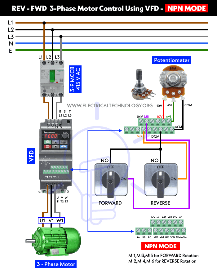
For NPN Mode:
- All the steps are the same as above, except the NO terminal of both the REV and FWD switches are connected to the DCM terminal of the VFD instead of the 24V terminal.
Programming the VFD for Reversal and Forward Operation
Since we are utilizing the Delta VFD in the above tutorial, you have the option to employ any of the following programming software that is compatible with your model. Examples include Delta VFDSoft, Delta VFD-M Series, CVFD for VFD Communication, and Delta FlashTool. For supplementary applications like linking the VFD to the PLC, the program should be capable of communicating with WPLSoft. Furthermore, for Delta AC Motor Drives such as MS300, MH300-L, VFD-E, CP2000, CT2000, CH2000, C200, etc., the software needs to have communication capabilities.
- Access the VFD’s programming interface. This is typically done via a keypad or a software interface.
- Configure the basic motor parameters, such as the rated motor voltage, current, and frequency.
- Set up the control inputs. Assign the digital inputs that correspond to the Forward and Reverse buttons.
- Enable the reverse function. In the VFD’s programming, set the REV command to be activated when the Reverse button is pressed.
- Enable the Forward function. Similarly, set the FWD command to activate when the Forward button is pressed.
- Set the acceleration and deceleration parameters to ensure controlled motor speed and smooth motor operation during start and stop.
With this setup, the motor can be controlled automatically and manually for reverse and forward operation. Some VFDs have dedicated buttons on their keypad for this purpose. Additionally, to manually change the direction of rotation of the motor, you can utilize the digital input terminals MI1 (for Reverse) and MI2 (for Forward).
You may optionally connect a PLC to the VFD using an RJ45 or RS485 connector for serial communication. For a Human Machine Interface (HMI), use RS485, while for computers, PCs, and laptops, use RS485 or RJ45 connectors.
Precautions
- Safety First: Always follow safety guidelines while working with electrical components. Ensure power is disconnected before making any connections.
- Proper Grounding: Ensure the motor, VFD, and control devices are properly grounded to prevent electrical faults and interference.
- Motor Protection: Configure the VFD’s motor protection features, such as overcurrent and thermal protection, to safeguard the motor from damage.
- Testing: Before running the motor in reverse or forward, perform a test in a controlled environment to ensure everything is working as intended.
- Regular Maintenance: Keep the VFD and motor well-maintained as per the manufacturer’s recommendations to prolong their lifespan and ensure optimal performance.
Related Posts:
- How to Run a Three-Phase Motor on Single-Phase Supply Using VFD?
- Automatic & Manual Control of Motor Using VFD & DOL Starter
- VFD Bypass Star-Delta Starter – Power and Control Circuits
- VFD Bypass DOL Starter – Power, Wiring and Control Circuits
- Reverse Forward Motor Control Circuit Using PLC & ZEN Programming Relay
- Reverse-Forward of 3-Phase Motor using DOL Starter
- Automatic Reverse – Forward Motor Control Circuit Using Omron CP2E PLC
- Automatic Reverse Forward Motor Control Using S7-1200 PLC
- ON / OFF 3- Phase Motor Using 14-PIN Relay and DOL Starter
- Automatic Star-Delta Starter using Timer – Power, Control & Wiring Diagrams
- Star – Delta Motor Control Circuit Using Omron PLC ZEN Programming Relay
- Sequential Motor Control Circuit Using LOGO! V8 PLC
- Sequential Motor Control Circuit Using Mitsubishi FX5U PLC
- Sequential Motor Control Circuit Using Delta – DVP-14SS PLC


