What is a VFD (Variable Frequency Drive)? – Circuit, Working, Types & Applications
Variable Frequency Drive (VFD) – Circuit Diagram, Working, Types, Advantage, Disadvantages, and Applications
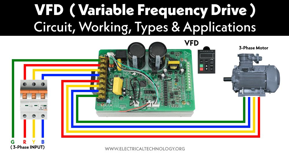
There are different types of large electrical motors used in industries that have very high power consumption. To increase the efficiency of AC electrical motors and also provide speed control, these motors are equipped with VFD (variable frequency drive). In addition to speed control, they also provide phase-protection, over-voltage protection and overcurrent protection.
What is a VFD?
VFD stands for Variable Frequency Drive. As its name suggests it is an adjustable frequency drive that varies the frequency of the AC supply. Since the speed of an induction motor depends on the supply frequency, the VFD can be used to vary its speed.
A VFD is a power converter that uses electronic circuits to convert a fixed frequency and fixed voltage into a variable frequency and variable voltage. It even enables a motor to run above its rated speed by increasing the frequency. Due to its programmable and easy to use UI (user interface), it can be easily used to monitor and maintain the speed of an electrical motor.
Circuit Diagram of VFD
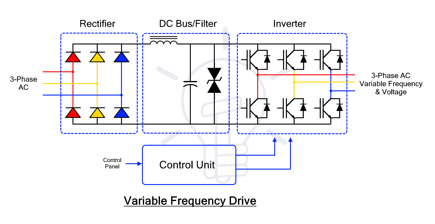
Generally, a VFD is made of four blocks or sections where each section has its own function. The four blocks or sections of a VFD are Rectifier, DC bus/filter, Inverter and Control Unit. The block diagram of a VFD is also given below.
Each block is explained in detail down below.
Working of VFD
The main function of a VFD is to vary the operating frequency of an AC supply. Simply put it converts the AC into DC and then into AC having adjustable frequency but the operation uses four blocks or sections of VFD. These sections are Rectifier Section, DC Bus / Filter Section, Inverter Section and Control Unit Section. Each one of the circuits is explained below.
The Rectifier
The input AC supply is connected to the Rectifier section of the VFD. It is a full-wave rectifier that converts the AC power into unfiltered DC.
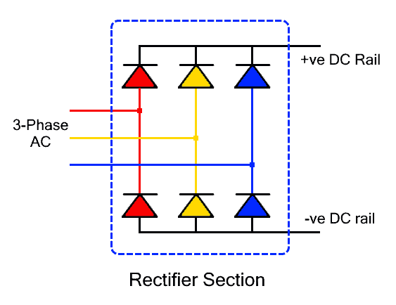
It is made of 6 or 4 diodes or thyristors. Six diodes are used for three-phase power conversion while 4 diodes in bridge configuration are used for single-phase AC power conversion. Whereas the diode rectifier is used for uncontrolled conversion while the thyristor offers controlled switching that varies the output DC power.
The given circuit represents a three-phase diode rectifier. It consists of 6 diodes where each phase is connected with a pair of diodes for rectification. Three of the six diodes are connected in forward bias with the positive DC output while the remaining three diodes are connected in reverse bias with the negative DC output.
The rectifier converts the sinusoidal input into a pulsating DC that swings between the maximum positive peak and zero volts. For a visual representation, the input and output waveforms are given with the circuit.
The DC Bus and Filter
This intermediate section is used for filtering and storing the DC power that is retrieved by the inverter. Its main function of filters is to remove the ripples from the pulsating DC output of the rectifier.

It is mainly made of capacitors to filter the ripples from the pulsating DC and also store it. It may include an inductor as well depending on the type of ripples.
The Inverter
This is the inverter or switching section that converts the steady DC into alternating AC with adjustable frequency.

It is made of power transistors or IGBTs. They switch rapidly to provide alternating voltage at the output. Its switching frequency determines the output AC frequency. Whereas, the switching rate of IGBTs is controlled through the control unit.
There are 4 IGBTs used for single-phase conversion while 6 IGBTs are used for three-phase power conversion.
- Related Post: What is DC Drive? Working and Types of DC Drives
The Control Unit
This section is the controlling unit responsible for controlling the switching operation, output frequency, output power. It is integrated with the user interface and sensors to acquire the necessary data. It also monitors fault conditions.
The control unit consists of an embedded microprocessor programmed for controlling the rectifier and inverter section. It can react in microseconds in case of any fault conditions. The feedback data from the speed sensor is used to monitor the speed as well as adjust it accordingly to the need.
Types of VFDs
There are three types of VFD classified based on the method of power conversion.
VSI type VFDs
The VSI or Voltage Source Inverter type VFD is the most common type. it provides a smooth voltage waveform that depends on the output frequency. It has a very simple design including a simple diode rectifier with a capacitor for filtering and storing DC energy. The DC voltage is then converted into AC using an inverter. They offer very good operating speed and control multiple motors.
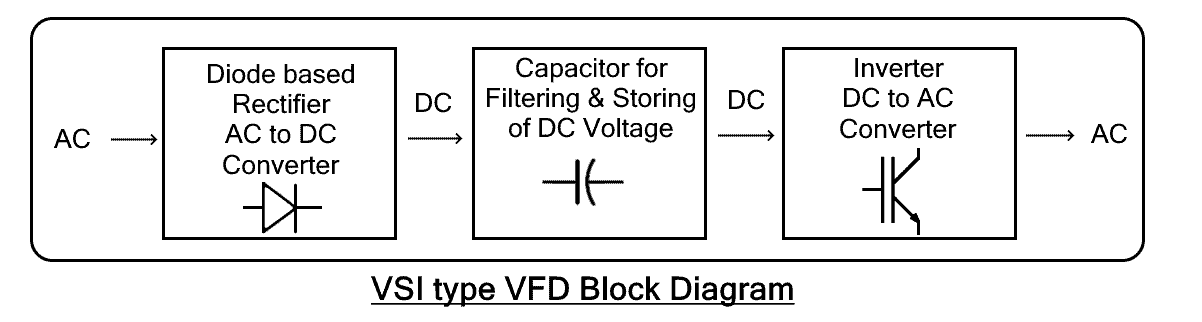
The drawback of VSI is that they have poor power factors as well as they cause motor cogging at a low frequency below 6 Hz. Apart from that, they are also non-regenerative i.e. they cannot store the energy flowing back from the motor.
Advantages
Here are some advantages of VSI based VFD
- It has a very simple design.
- It is very cheaper and cost-effective.
- It offers a very good operating speed range
- It can control multiple motors.
Disadvantages
Here are some disadvantages of VSI based VFD
- It has a very poor power factor, especially at low speed.
- It causes the motor to cog below 6Hz frequency.
- The cogging causes the motor to jerk at starting and stopping.
- Different harmonics are generated at its output.
- They are non-regenerative.
Related Post: Difference between AC Drives and DC Drives
CSI type VFDs
CSI or Current Source Inverter type VFD provides a smooth current waveform as opposed to the smooth voltage waveform of the VSI type. It utilizes large inductors and expensive inductors to store and deliver steady DC current.
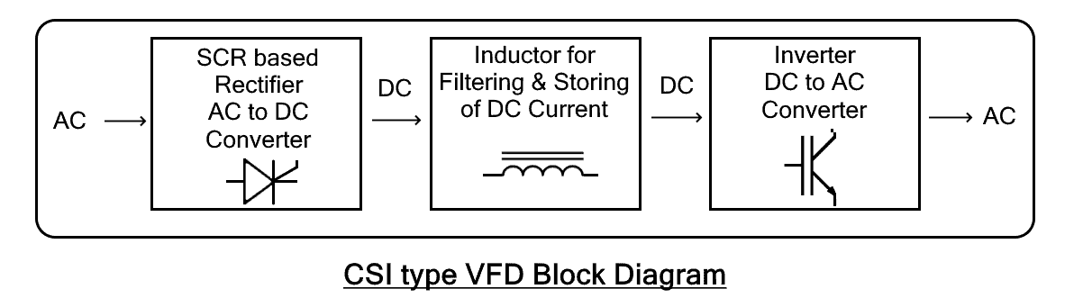
It is made of SCR-based rectifiers for AC to DC conversion with a series of inductors for filtering and storing the DC current. The inverter converts the DC current into alternating current.
The CSI-type VFDs have regenerative power capabilities i.e. they store the energy that flows back from the load such as a motor. but they also cause motor cogging at a low frequency below 6Hz. They are mostly used in signal processing.
Advantages
Here are some advantages of CSI based VFD
- It has regenerative capabilities to absorb the power coming back from the motor.
- It acts as a constant current source that supports high-power motors.
- It has a very simple design.
- It is more reliable than VSI type VFD.
Disadvantages
Here are some disadvantages of CSI based VFD
- It has a poor power factor, especially at low speed.
- The inductors are very large and expensive.
- Overall CSI VFD is expensive than VSI VFD.
- It causes cogging effect creates jerks in the motor shaft during starting and stopping.
- Unlike the VSI type, it cannot run multiple motors at once.
Related Post: Speed Control of DC Motor – Voltage, Rheostatic & Flux Control Methods
PWM type VFD
PWM or Pulse Width Modulation is a technique where the duty cycle of a signal is varied to vary the average power delivered. PWM-based VFD uses fixed DC voltage pulses of different duty cycles to simulate a sinusoidal waveform. It is an improved version of VSI, therefore, it provides stable voltage with an improved power factor.
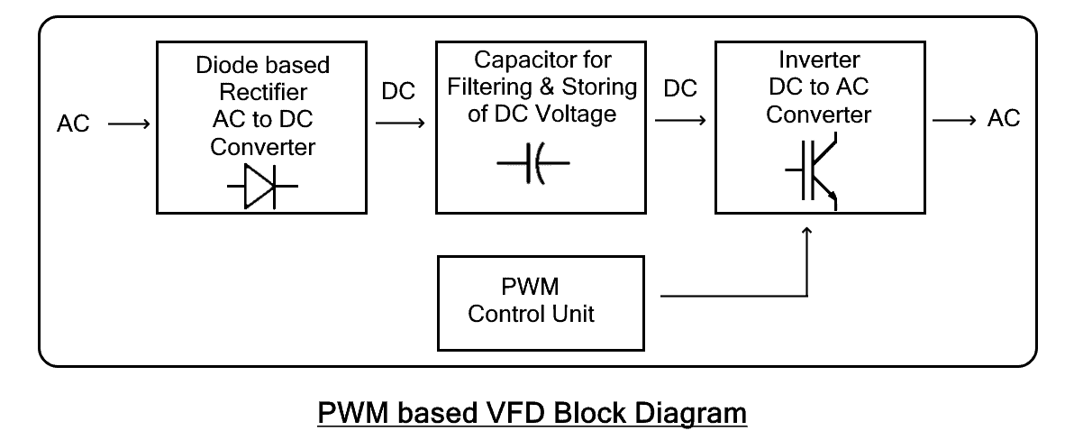
It has a simple diode bridge rectifier that converts AC into DC. The Control Unit is programmed to control the duty cycle of the inverted output by adjusting the switching speed of the inverter. It also requires an extra regulator at its output to regulate the voltage pulses and provide a smooth voltage and current waveform.
It is the most common method used in VFDs due to its numerous advantages over the VSI and CSI VFD. For instance, it does not cause cogging in motor with improved efficiency. It has a better power factor. But they are quite complex to design and implement. They also require an additional circuit for voltage and current regulation.
Advantages
Here are some advantages of PWM based VFD
- It has an improved power factor.
- It does not cause cogging in motors.
- It has much better efficiency than VSI and CSI.
Disadvantages
Here are some disadvantages of PWM based VFD
- It has a complex design and implementation.
- It requires an additional hardware circuit, regulator.
- It is expensive than VSI and CSI.
Advantages of VFD
VFD not only provides variable speed control but also offers energy saving with improved efficiency and simple control. Here are some of the advantages or benefits of VFD
Improved Efficiency: The conventional speed control using the variable voltage method wastes a lot of energy as compared to the variable frequency method. Therefore, VFD is used in industries to increase motor efficiency and conserve a great amount of energy.
Precise Control: A VFD allows tighter control of the speed using a sensor to run the motor at an efficient speed that does not cause hindrance and increases the production speed in the industries.
Limits Inrush Current: Inrush current is the huge starting current drawn by an induction motor during its startup. it is 5 to 8 times greater than its rated current. It can damage the windings of the motor. The VFD can safely limit the starting current and it is used in one of the methods for induction motor starting.
Extend Mechanical Life: It can safely start and stop a motor with a gradual change in speed without any mechanical jerks. It extends the mechanical life of the motor.
Reduced Maintenance: Smooth operation of motors reduces the mechanical stress and eliminates the jerks that eventually reduce the maintenance required for such motor. Thus reducing the long-term cost.
Power Factor: A poor power factor causes reactive power loss that is the energy wasted in the form of heat. Induction motor usually has a low power factor. A VFD improves the power factor to utilize the power more efficiently.
Protection: A VFD can also provide protection against overload, over-voltage and phase loss. It immediately stops the supply current in case of such faults to protect the load connected from damage.
Easy installation: They are easier to install and operate since they are programmed during manufacturing with easy to operate and friendly user interface.
Disadvantages of VFD
VFD has many advantages but they all come with some cost. Here are some disadvantages of VFD.
Initial Cost: VFDs are expensive than direct on-line or across the line motor starter. Therefore, the initial cost for the installation of VFDs in a large factory is fairly high.
Special Motor Design: The PWM-based AC output of VFD is not pure sinusoid. It can create stress in the windings of a normal AC motor that can heat up and degrade the winding insulation. Therefore, a special motor with improved insulation design rated for PWM inverter is required for running with VFD.
Harmonics: The VFD can create harmonic in the supply. The non-linear current draw of the rectifier circuit creates distortion in the supply that affects the electrical equipment connected in parallel. Therefore, it requires extra harmonic filters.
Complex Operation: As compared to direct on-line DOL or across the line starter, the operation and settings of VFD is complex. Modern VFDs have a more user-friendly interface, but still, it cannot compete with the direct on-line starter simple push-button operation.
Extreme Environment: As compared to the DOL starter, the electronic circuitry in VFD is sensitive and its operation is affected by extreme cold or heat. It requires additional measures to cope with such an extreme environment.
Application of VFD
The main function of a VFD is to vary the supply frequency of AC but it can also vary the voltage. Here are some applications of VFD.
- The variable-frequency feature is used for controlling the speed of induction motor whose speed only depends on frequency.
- It is used for precise motor speed control with smooth starting and stopping in conveyor belt systems to avoid any accidents and have increased production.
- The precise speed control is also used in the cooling system to maintain temperature.
- Lifts and escalators use the smooth start and stop feature of VFD.
- They are used for water pumps and also for crushers in mining.
- Hoist and crane use VFD for precise control of speed and positioning.
Related Posts:
- What is Soft Starter? Its Working, Diagram and Applications
- Star Delta Starter – (Y-Δ) Starter Power, Control and Wiring Connection
- STAR-DELTA Starter Motor Starting Method Without Timer
- Direct Online Starter – DOL Starter Wiring Diagram for Motors
- What is Motor Starter? Types of Motor Starters and Motor Starting Methods
- Motor Protection – Types of Faults and Protection Devices
- Types of Electric Motors – Classification of AC, DC & Special Motors
- What is a Contactor ? Types, Working and Applications
- Why We Need to Install a Starter with a Motor?
- Single-Phase Induction Motor – Construction, Working, Types & Applications
- Three-Phase Induction Motor – Construction, Working, Types & Applications


