Reverse Forward Motor Control Circuit Using PLC – ZEN Programming Relay
How to Control the Reverse Forward Motor Operation Using Omron PLC ZEN Programming Relay?
In industrial applications, motor control circuits are used to control the speed, direction, and braking of electric motors. One common method of controlling the direction of rotation of a motor is the reverse forward motor control circuit. In this circuit, a motor can be made to rotate in both directions by using two contactors, one for forward direction and the other for reverse direction. The Omron PLC ZEN programming relay is an ideal choice for implementing the reverse forward motor control circuit.
The Omron PLC ZEN programming relay is a compact and cost-effective programmable logic controller that can be used for a wide range of applications. The ZEN relay is equipped with a user-friendly programming interface that allows for easy implementation of control circuits, such as the reverse forward motor control circuit.
The reverse forward motor control circuit using the Omron PLC ZEN programming relay consists of two contactors, a power supply, and the ZEN relay. The contactors are used to switch the motor connections between the power supply and the motor terminals, allowing the motor to rotate in either direction. The ZEN relay is used to control the contactors and to implement the control logic for the circuit. (We have used 10C1AR-A-V2 (100-230V AC) and 10C3D -D-V2 (24V DC) programable relays in this tutorial).
Related Posts:
- Automatic Reverse – Forward Motor Control Circuit Using Omron CP2E PLC
- Automatic Reverse Forward Motor Control Using S7-1200 PLC
Hardware Required
The following hardware components are required to implement the automatic control of reveres-forward motor rotation:
- ZEN Programable Relay – ZEN V2, ZEN PA, ZEN 10C etc.
- Induction Motor
- 3P MCCB
- 2P MCB
- 2 Nos of Magnetic Contactors
- Thermal Overload Relay
- 2 Nos of NC Push Buttons Switches
- 400-480V Three Phase supply
- 230V Single Phase Supply
Power, Wiring & Ladder Control Diagrams
Wiring Diagrams
Click image to enlarge


Related Post:
- Reverse Forward Motor Control Circuit Using Mitsubishi FX Series PLC
- Automatic Reverse Forward Motor Control Circuit Using Delta – DVP-14SS PLC
To implement the reverse forward motor control circuit using the Omron PLC ZEN programming relay, the following steps can be followed:
- Power the Omron PLC ZEN programming relay using the power supply.
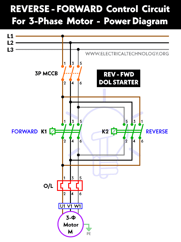
- Connect the motor to the two magnetic contactors. The motor terminals should be connected to the contactors’ output terminals, and the input terminals of the contactors should be connected to the power supply as shown in the power and wiring diagrams. Do the same for the thermal overload relay and wire it to the PLC relay.
- Connect the ZEN relay to the contactors. The ZEN relay’s output terminals should be connected to the input terminals of the contactors.
- Program the ZEN relay to control the contactors. The ZEN relay can be programmed to control the contactors in such a way that the motor can be made to rotate in both directions. For example, to rotate the motor in the forward direction, the ZEN relay can be programmed to activate the forward contactor (KM1) and deactivate the reverse contactor (KM2). To rotate the motor in the reverse direction, the ZEN relay can be programmed to activate the reverse contactor (KM2) and deactivate the forward contactor (KM1).
- Test the circuit. Once the circuit is programmed, it can be tested by applying power to the circuit and observing the motor’s rotation in both directions.
Related Posts:
- Star – Delta Starter Motor Control Circuit Using S7-1200 PLC
- Automatic Star – Delta Starter Motor Control Circuit Using LOGO! V8 PLC
Power Diagram
Ladder Control Diagram

Related Posts:
- Star Delta Motor Control Using Schneider Zelio Logic PLC Smart Relay
- Star – Delta Motor Control Circuit Using Delta – DVP 14SS2 Series PLC
Programming
To program the Omron ZEN programming relay for forward and reverse control of a three-phase motor, follow these steps:
Step 1: Open the ZEN programming software (ZEN-SOFT01-V4 or CX-Programmer) or and create a new project.
Step 2: Add a new program to the project and select the ZEN relay model that will be used in the circuit.
Step 3: Set the input and output points for the relay. The input points are used to control the direction of the motor, while the output points are used to control the contactors that switch the power supply to the motor.
Step 4: Define the input and output points for the forward and reverse contactors. The input points for the forward contactor should be connected to the output points for the reverse contactor, and vice versa.
Step 5: Program the relay to control the contactors based on the input signals. To rotate the motor in the forward direction, the forward contactor should be activated, while the reverse contactor should be deactivated. To rotate the motor in the reverse direction, the reverse contactor should be activated, while the forward contactor should be deactivated.
Step 6: Define the start and stop buttons for the motor. These buttons can be connected to input points on the ZEN relay and programmed to start and stop the motor based on the direction of rotation.
Step 7: Test the circuit by connecting the ZEN relay to the contactors and the motor. Apply power to the circuit and press the start button to test the motor’s rotation in both directions.
The reverse forward motor control circuit using the Omron PLC ZEN programming relay offers several advantages over traditional motor control circuits. First, the ZEN relay provides a compact and cost-effective solution for implementing the control logic for the circuit. Second, the ZEN relay’s user-friendly programming interface makes it easy to program the control logic for the circuit. Finally, the circuit is easy to maintain and troubleshoot, as the ZEN relay provides diagnostic information that can be used to identify and resolve any issues that may arise.
Related Power & Control Wiring Diagrams for Motors
- Reverse / Forward Circuit for 3-Phase Motors – Power & Control Diagrams
- Star – Delta Motor Control Circuit Using Omron PLC ZEN Programming Relay
- Star/Delta Starter Using a Programmable Logic Controller (PLC) – Ladder & Wiring Diagrams.
- Automatic Star-Delta Starter using Timer – Power, Control & Wiring Diagrams
- STAR/DELTA Starter Without Timer – Power, Control & Wiring Diagrams
- Reverse/Forward Circuit for Motors using Start Delta & Timer – Power & Control Diagrams
- Automatic Sequential Operations of Motors – Power, Control, PLC & Wiring Circuits
- Three Phase Slip Ring Rotor Starter – Control & Power Diagrams
- Starting & Stopping of 3-Phase Motor from More than One Place – Power & Control Diagrams
- ON / OFF Three-Phase Motor Circuit – Schematic Power, Control & Wiring Diagrams
- Controlling of 3-Phase Motor from More than Two Places – Power & Control Diagrams
- Multispeed (2 Speeds, 2 Directions) 3-Phase Motor Power & Control Diagrams
- Multispeed (2 Speeds, 1 Direction) 3-Phase Motor Power & Control Diagrams
- Multispeed (3 Speeds, 1 Direction) 3-Phase Motor – Power & Control Diagrams


