Sequential Motor Control Circuit Using LOGO! V8 PLC
How to Run Three Phase Motors in Sequence Using Siemens LOGO! V8 PLC?
LOGO! V8 is a programmable logic controller (PLC) manufactured by Siemens. It is widely used for automation and control applications in various industries. One common application is controlling and sequencing 3-phase motors. In this article, we will discuss the step-by-step process of running 3-phase motors in sequence using LOGO! V8 PLC.
Sequential Motor Control Circuit
A sequential motor control circuit is a circuit designed to control the operation of multiple motors in a specific sequence. It utilizes various control components such as relays, timers, and contactors to activate and deactivate the motors in a predetermined order.
The circuit ensures that the motors start and stop in a sequence, allowing for smooth operation and preventing overload or mechanical stress. Sequential motor control circuits find applications in various industrial processes, automation systems, and even in home appliances where synchronized motor operation is required.
The circuit design may vary depending on the specific requirements, but the basic principle remains the same: controlling the motors sequentially to achieve the desired operation.
Related Posts:
- Automatic Sequential Operations of Motors – Power, Control, PLC & Wiring Circuits
- Sequential Motor Control Circuit Using PLC S7-1200
Hardware & Components Required
To implement the sequential motor control circuit using LOGO! 8 PLC, the following hardware components are required:
- A LOGO! V8 PLC unit with the necessary power supply and programming cable.
- Three phase motors
- Motor starters and contactors
- MCBs and MCCBs
- Auxiliary relays (if needed)
- AC Supply (415V, 3-Phase & 230V 1-Phase)
- Start and Stop pushbuttons
Circuit Diagrams
Wiring & Power Diagram
Click image to enlarge
![]()
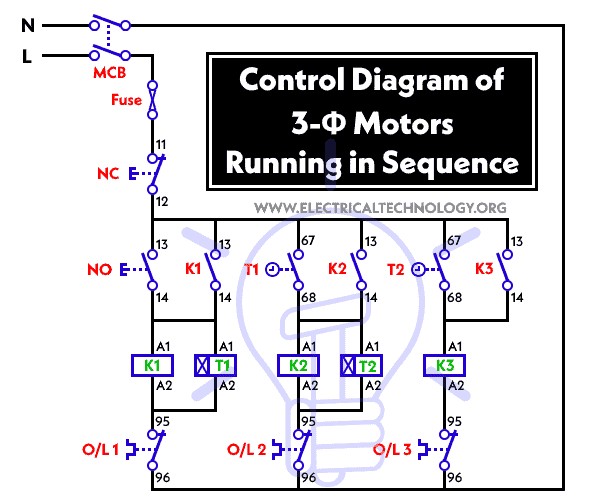
Control Diagram
Ladder Logic Diagram
![]()
Related Posts:
- Sequential Motor Control Circuit Using Delta – DVP-14SS PLC
- Sequential Motor Control Circuit Using ZEN Programable Relay
Programming the LOGO! 8 PLC for Sequential Operation
Before proceeding with the programming steps, ensure that you have the basic understanding of PLC programming concepts and LOGO! V8 software.
Step 1: Hardware Setup:
- Connect the LOGO! V8 PLC to the power supply and ensure that it is properly grounded.
- Connect the programming cable to the LOGO! V8 PLC and the other end to your computer or laptop.
- Connect the necessary input and output terminals of the PLC to the respective control components such as contactors and 3-phase motors (use I1, I2, I3 etc for input and Q1, Q2 Q3 for output) as shown in the power diagram.
Step 2: LOGO! Soft Comfort Software:
- Install the LOGO! Soft Comfort software (LOGO! 8.3) on your computer if you haven’t already. This software is used for programming the LOGO! V8 PLC.
- Launch the software and create a new project by selecting “New” from the “File” menu.
- Configure the PLC settings, such as the communication interface and address, by selecting “Device” from the menu and then “Device Configuration.”
- Define the inputs and outputs based on your hardware connections. For example, if you have push buttons as inputs and contactors as outputs, assign the appropriate addresses to them.
Step 3: Programming the Sequence:
- In the LOGO! Soft Comfort software, select “Program” from the menu and then “Function Block Editor.”
- Create a new function block diagram (FBD) by clicking on the respective icon.
- Add the necessary function blocks to the FBD editor. For running 3-phase motors in sequence, you will need timer function blocks, contactor coils, and branching blocks.
- Use a timer function block to set the time delay between the activation of each motor.
- Connect the input push buttons to the coil of the first contactor. Use a normally open (NO) contact from the first contactor to control the coil of the second contactor, and so on. This ensures that the motors are started in sequence.
- Use timers to introduce the desired delay between the activation of each contactor coil.
- Add branching blocks to create conditional statements. For example, if a stop button is pressed, the sequence should stop, and all contactor coils should be de-energized.
Note: As an example, you may design the program based on the given ladder diagram above.
Step 4: Download and Test the Program:
- Connect the LOGO! V8 PLC to your computer using the programming cable.
- Download the program to the PLC by selecting “Transfer” from the menu and then “Download.”
- Once the program is successfully downloaded, disconnect the programming cable from the PLC.
- Test the sequence by pressing the start button and observe the activation of the contactors in the desired sequence. Verify that the motors start one after another with the specified time delay.
- Test the stop functionality by pressing the stop button and ensuring that all motors stop running.
Related Motor Control & Power Diagrams:
- Star – Delta Motor Control Circuit Using Omron PLC ZEN Programming Relay
- Star – Delta Starter Using Different PLCs – Wiring and Ladder Diagram
- Automatic Reverse Forward Motor Control Circuit Using Delta – DVP-14SS PLC
- Automatic Reverse – Forward Motor Control Circuit Using Omron CP2E PLC
- Star – Delta Motor Control Circuit Using Delta – DVP 14SS2 Series PLC
- Star – Delta Motor Control Using Schneider Zelio Logic PLC Smart Relay
- Reverse Forward Motor Control Circuit Using PLC – ZEN Programming Relay
- Reverse Forward Motor Control Circuit Using Mitsubishi FX Series PLC
- Automatic Reverse Forward Motor Control Using S7-1200 PLC
- Automatic Star – Delta Starter Motor Control Circuit Using LOGO! V8 PLC
- Star – Delta Starter Motor Control Circuit Using S7-1200 PLC
- STAR/DELTA Starter Without Timer – Power, Control & Wiring Diagrams
- Reverse/Forward Circuit for Motors using Start Delta & Timer – Power & Control Diagrams
- Even More Motor Control Circuits and Diagrams


Thank you.
That’s good.