Wiring a Smart Wi-Fi Switch with and without Neutral in a Conventional and Smart 120/240V Panels
Smart home automation systems make everyday living more convenient, efficient, and comfortable by seamlessly integrating intelligent devices into the home environment. They are especially valuable for individuals who feel uneasy about managing complex wiring and electrical conductors, as modern smart solutions minimize visible cables and reduce manual intervention.
By combining wireless connectivity, intuitive controls, and automated routines, smart homes transform traditional living spaces into responsive environments that adapt to user preferences. From voice-activated lighting and climate control to automated security monitoring, these systems enhance safety, conserve energy, and simplify daily tasks.
Ultimately, smart home automation is not just about technology, it is about creating a streamlined, future-ready living experience that prioritizes comfort, control, and peace of mind.
What is a Smart Switch?
A smart switch is a modern wall-mounted device designed to replace a traditional light switch while adding network connectivity and intelligent control. Unlike standard mechanical switches, smart switches connect to your home Wi-Fi system, allowing users to control lighting and other electrical loads remotely through mobile apps, voice assistants, or smart home platforms.
These smart switches are available from different manufacturers such as Leviton and Legrand. These devices support features like scheduling, scene control, device grouping, and multi-location operation. The operation of the these smart devices can be controlled from anywhere using mobile app and are compatible with Hey Google (Google Home), Amazon Alexa, Apple Homekit (Siri) and SmartThings etc.
Smart switches are widely used in residential and light commercial environments to enhance lighting control and automation. They are commonly installed in living rooms, bedrooms, kitchens, hallways, and outdoor lighting circuits where remote access and programmable schedules improve convenience and safety.
Users can automate lights to turn on at sunset, switch off when rooms are vacant, or coordinate multiple switches to create customized lighting scenes. In advanced smart home ecosystems, Matter-enabled and mesh-connected switches enable reliable, low-latency communication and scalable control across larger properties.
The advantages of smart switches center on convenience, energy efficiency, and seamless integration with broader smart home systems. Remote access allows users to monitor and control lighting from anywhere, helping reduce unnecessary energy consumption and enhance home security.
Voice assistant compatibility enables hands-free operation, while cross-platform support ensures flexibility across devices and brands. Automation, scheduling, and multi-location control further improve comfort, operational efficiency, and overall user experience without requiring complex rewiring.
Good to Know:
- Smart switches are different from standard lighting switches. They are not wired the same for single and multi-way applications. See the folloiwing wiring diagrams.
- Smart switches are available in 15A/120V without neutral (DN15S) for single, and with neutral (D315S, D215S, WNRL10, WWMRL10) for 3-way, multi-way wiring.
- ON/OFF and scheduling features can be controlled using Legrand Home + Control or My Leviton App.
Rating & Features of a Smart Switch
- Name: Smart Wi-Fi Switch
- Poles: Single-Pole, 3-Way & Multiway – With and Without Neutral
- Voltage: 120V Single-Phase AC Supply – 60 Hz
- Current: 15A General & 5A LED/CFL or Electronic Ballast
- Wattage: 1500 – 1800W Incandescent/Halogen Lamps or ¾ to ½ HP Motor
- Wire Size: #14 – #12AWG Copper
- Bridge / HUB: Yes & NO
- Termination: Wired Leads, Back Wired & Side Wired for other smart devices – Screw Termination and Mounting
- Frequency: 2.4 GHz – 801.11b/g/n Networks
- Bluetooth: v5.0
- Range: 30 to 50 ft (≈ 9 – 15 meters)
- Compatibility: Amazon Alexa, Google Assistant (Hey Google / Google Home), Apple HomeKit/Siri, Samsung SmartThings, Matter. Sonos, Schlage Encode™ & IFTTT services.
Wiring Configurations of a Smart Switch
Wiring a Smart Switch in a Smart Load Center – Neutral Required
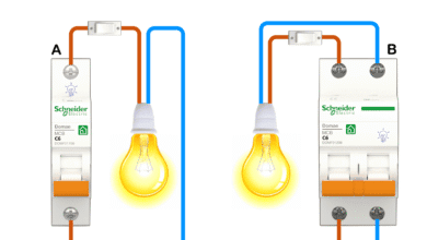
The following wiring diagram shows a 15A – 120V smart Wi-Fi switch is used to control the lighting point. The smart switch is wired through a 15A – 120V smart breaker in the smart 120/240V breaker box.
As shown in the fig for smart switch installation:
- The hot (black) wire from the breaker connects to the “LINE” terminal
- The neutral (white) from the breaker connects to the “N” terminal.
- The ground (bare or green) conductor from the main panel connects to the “G” terminal.
- The load line (black) from the light connects to the “Load” terminal.
- As the switch is used to control a single load, the traveler “T” terminal on the smart switch is pig-tailed and unused.
Click image or open in a new tab to enlarge
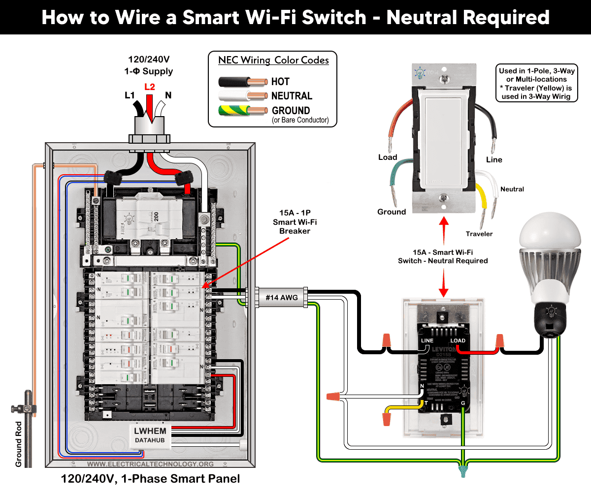
Good to Know: For single load application, the wiring method is same for all smart switches by Leviton i.e. D315S, D215S, DN15S, ZW15S, D26HD, D2SCS etc.
Wiring a Smart Switch in a Conventional Panel – No Neutral Required
All the wiring is same as above except there is no neutral wire is used from neutral busbar in the conventional 120/240V load main panel to the smart switch.
It can also be used for wire-free three-way switching when used with Anywhere Switch Companion devices. In addition, it requires MLWSB Wi-Fi Bridge for smart controlling and operation.
Click image or open in a new tab to enlarge
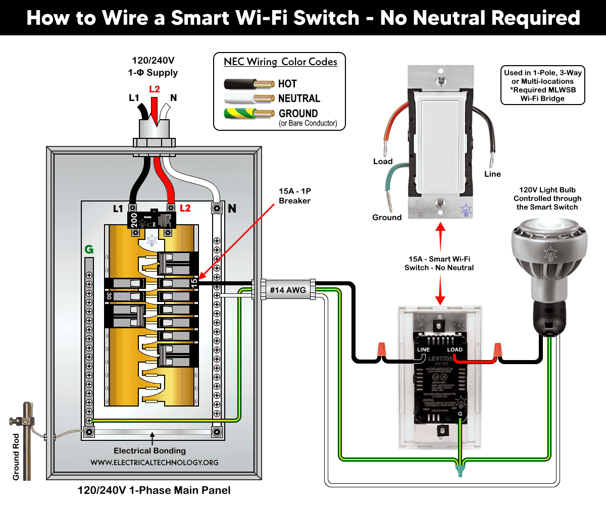
Good to Know: This case is a perfect choice for retrofit where a neutral wire may not be presented in the switch wall box especially in older home.
Wiring a Smart Switch with a Smart Switch Companion for Multi-Location Switching
The wiring diagram below shows a 15A smart switch (D315S or D215S) is wired with a smart switch companion (DD0SR) for multi-location switching as follow:
Click image or open in a new tab to enlarge
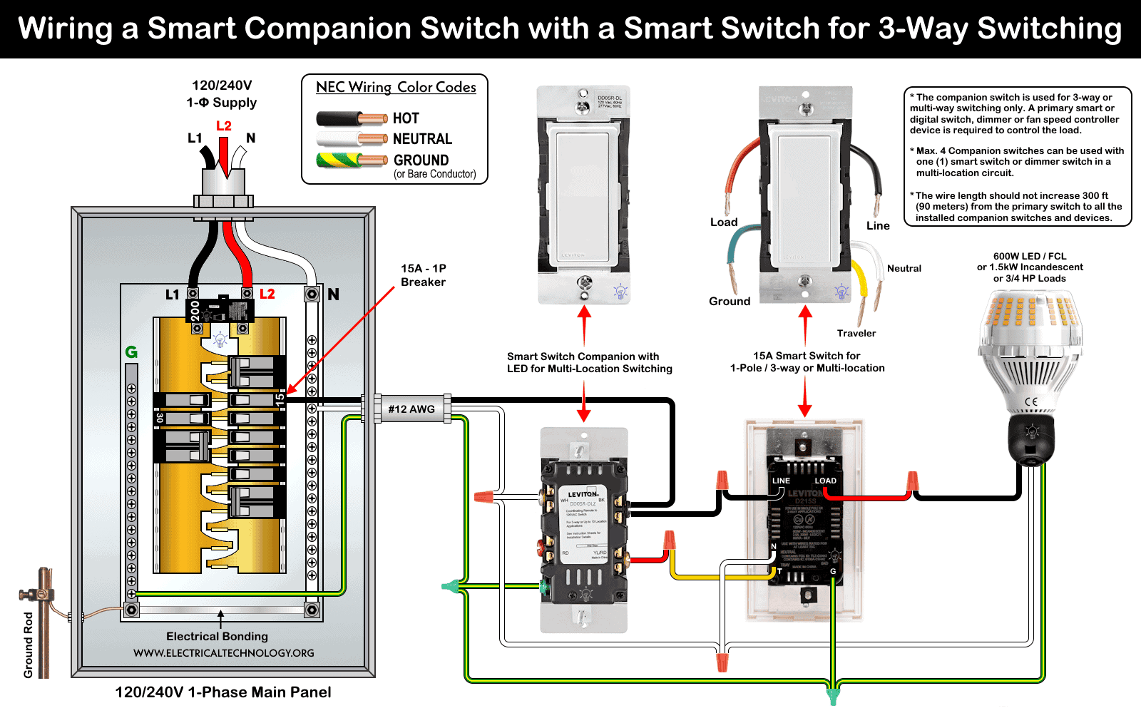
- The “N” and “WH” terminals of both (smart and companion) switches are wired to the neutral (white) conductor as well as load from neutral busbar in the main panel.
- The “LINE” terminal of smart switch is wired to the hot (black) conductor from the breaker. The “BK” terminal (black screw) on companion switch is un-used in this case.
- The “Green” and “G” terminals of both switches are wired to the bare or green conductor as well as the load from the ground busbar in the main panel.
- For three-way switching, the “T” terminal of the smart switch in box 1 is connected to to the “YL/RD” terminal of companion switch in the second box.
- The “Load” terminal of the smart switch is connected to the load as hot (line).
If properly installed, the lighting point or any other connected load can be controlled manually and remotely from different locations.
Good to Know:
- If wiring with a digital dimmer (such as DDL06) with a smart switch (such as DD0SR), the neutral conductors are remain un-used (not connected) and tied together in the box.
- If Neutral is available, the BK and RD terminals are not used when withing with smart companion (such as DD0SR). This case is shown in the wiring of digital dimmer switch with smart companion switches.
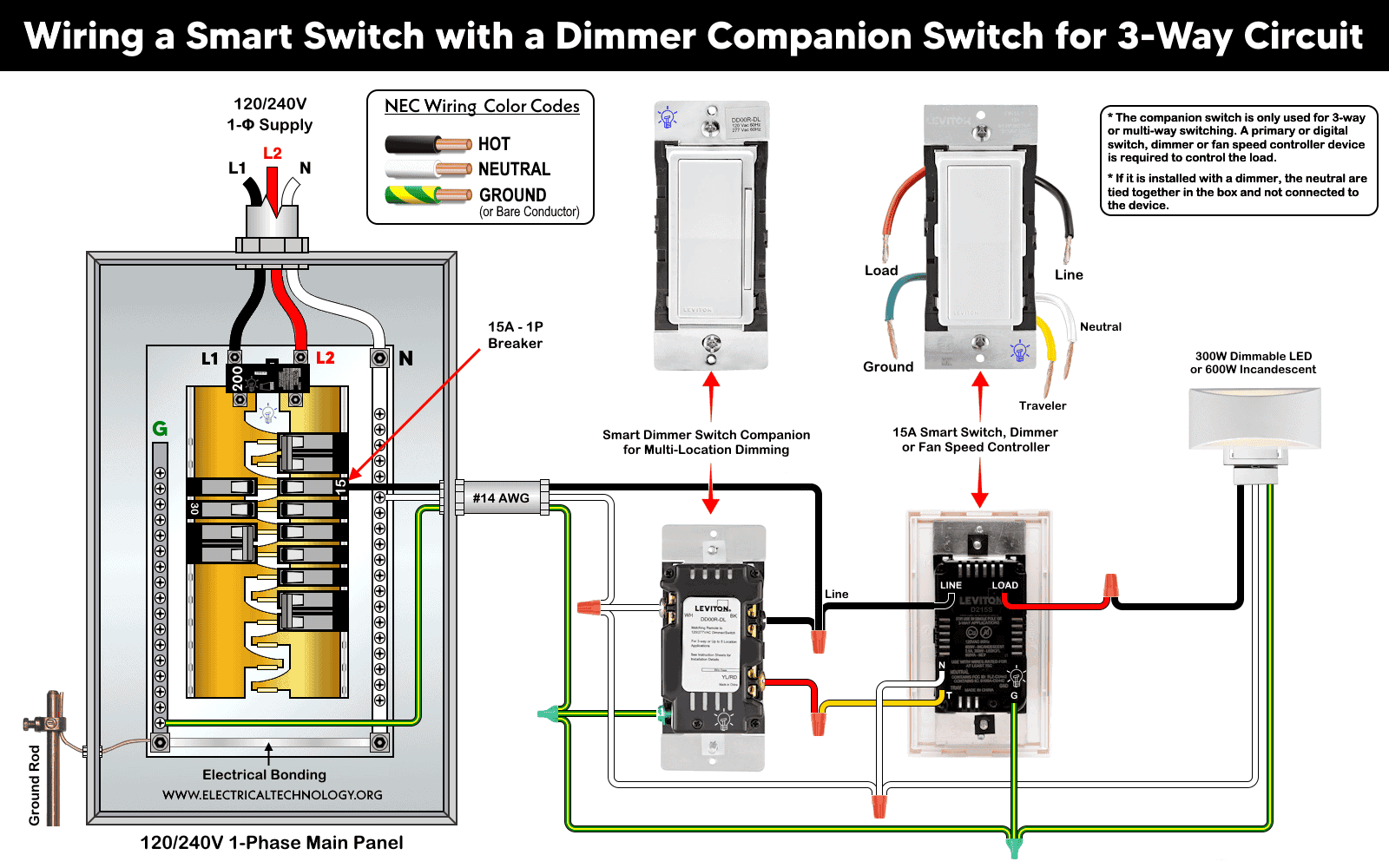
Wiring a Smart Switch with a Smart Dimmer Companion Switch for Multiway Circuit
In this wiring diagram, a 15A smart switch (D315S / D215S) or smart fan speed controller is used with a smart dimmer switch companion (DD00RL) for multi-location dimming (multi-way circuit).
As shown,
- The “LINE” and “BK” terminal of both (smart and companion) switches are wired to the hot (black) conductor from the breaker.
- The “N” and “WH” terminals of both switches are wired to the neutral (white) conductor as well as load from neutral busbar in the main panel.
- The “Green” and “G” terminals of both switches are wired to the bare or green conductor as well as the load from the ground busbar in the main panel.
- For three-way operation, the “T” terminal of the smart switch in box 1 is connected to to the “YL/RD” terminal of companion switch in the second box.
- Finally, the “Load” terminal of the smart switch is connected to the load as hot (line).
This way, the lighting point can be controlled manually and remotely from two different locations.
Click image or open in a new tab to enlarge
Good to Know:
- It can also be used for wire-free three-way switching when used with Anywhere Switch Companion devices. In addition, it requires MLWSB Wi-Fi Bridge for smart controlling and operation.
- The Decora smart switch by Leviton is not compatible with ordinary 3-way or 4-way switches.
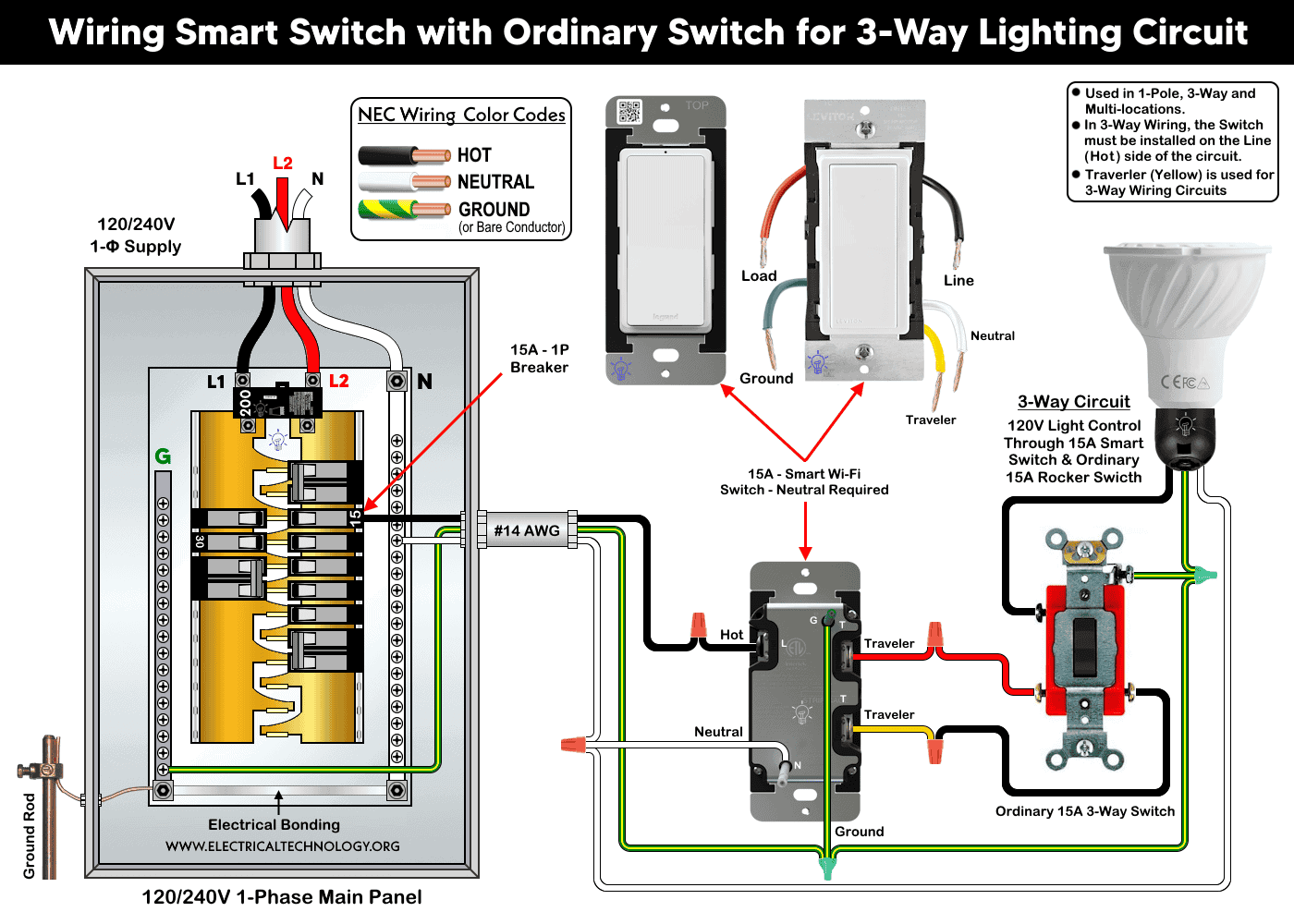
Wiring a Smart Switch with an Ordinary Switch for 3-Way Lighting Circuit
If you are not OK to use a companion switch with a smart switch for 3-way lighting control, you may use an ordinary 3-way switch with a smart switch to do so as shown below.
In this configuration for 3-way smart switching:
- The #14AWG hot (black) wire from the 15A breaker connects to the “black” screw of smart switch
- The neutral (white) from the breaker connects to the “N” terminals and silver screw of both switches as well as load point.
- The ground (bare or green) conductor from the main panel connects to the “G” terminal and green screw of both both switches as well as load point.
- The travelers from smart switch in box 1 (red wire and yellow/black wires) connects from brass screw to the brass terminal of rocker 3-way switch located in box 2.
- Finally, the load hot (black) from the black screw of ordinary 3-way switch connects to the the light.
If wired correctly, the light bulb can be controlled remotely as well as manually from two different locations.
Click image or open in a new tab to enlarge
Good to Know:
- This system can be wired for 1-pole, 3-way and multi-locations controlling.
- Travelers (yellow) is not used for single load application i.e. it is especially used for 3-way wiring circuits.
- In 3-way wiring, the smart switch must be installed on the Line (Hot) side of the circuit.
Adding to the Network and App
Hold the top rocker for 7 seconds and release when the status light turns Amber. When the status light flash green, the device is now in the setup up mode to add in a network.
For Leviton smart switches, use the My Leviton app with Leviton Decora Smart devices. For Legrand smart switches, use the Home + Control app. Both applications are available on the Google Play Store (Android) and Apple App Store (iOS).
After installation, Tap the “+” and select “add a device”, follow the on-screen instructions within the respective app to add and configure your smart switch. Once set up, you can control your lighting remotely and enjoy the convenience and peace of mind that comes with a connected smart lighting system.
Troubleshooting via LED Status Indictor
The following table shows the troubleshooting and diagnostic of smart switches by Leviton and Legrand using the built-in LED status indicator on it.
| Smart Switch LED Status Indicator | ||
| For Leviton Smart Switches | ||
| LED Color | Status | Indication |
| Green | Flashing | Setup Mode – Add to a Wi-Fi Network |
| Green | Slow Blinking | Connecting to a Wi-Fi Network |
| Green/ OFF | Solid | Normal Operation |
| Amber | Slow Blinking | Not Connected to the Wi-Fi Network |
| Green/ Amber | Alternating Blinking | Device is in Wireless Mode |
| Red | Blinking | Warless Device is unpaired |
| Green/Red/Amber | Alternating Blinking | Feature triggered from the App |
| For Legrand Smart Switches | ||
| Green | Blinking | Setup Mode – Add to a Wi-Fi Network |
| Green | Solid | Device in Network – Currently Open. |
| White | Solid | Device is connected but Switched-Off |
| Green/Red | Blinking | Device is being reset to Factory Default. |
| Red | Solid | Not in Network – Factory Reset |
Instructions & Precautions.
- Always disconnect the power supply by switching OFF the circuit breaker at the main service panel before performing any electrical work.
- According to NEC Tables 310.16, 210.24(1), and 240.4(D)(4), the correct breaker and conductor size for a 15A, 120V circuit is #14 AWG copper. Therefore, use #14 AWG copper or copper-clad conductors with 15A smart switches, breakers and receptacles.
- For conductors other than factory-stripped ends, strip:
- 3/4 in. (19 mm) for side wiring, and
- 1/2 in. (12.7 mm) for back wiring.
- Tighten all terminal screws to 14-18 in·lb (1.6-2.0 N·m) of torque, or according to the manufacturer’s specified termination range.
- The wire length between the smart switch and any companion device must not exceed 300 ft (90 m).
- 15A/120V switches and receptacles must be installed on a 15-amp breaker only.
- Smart devices are intended for indoor use only.
- If you are unsure about any part of the installation, consult a licensed electrician and ensure compliance with applicable local electrical codes.
Disclaimer:
The author assumes no responsibility for any loss, injury, or damage resulting from the use or misuse of this information, including improper circuit installation. Electrical work can be hazardous. Always exercise extreme caution when working with electricity.
Resources:
Smart Devices Wiring Series
- How to Wire 120/240V Smart Load Center with Smart Breakers
- How to Wire a Smart Breaker in a Smart 120/240V Panel
- How to Wire a Smart GFCI Breaker in a 120/240V Smart Panel
- How to Wire Smart AFCI/GFCI Breaker in a Smart Load Center
- How to Wire a 15A Wi-Fi Smart Outlet in a Smart Panel
- How to Wire 15A and 20A Wi-Fi Smart GFCI Outlets
Main Panels Wiring Tutorials
- How to Wire 120/240V Main Panel – Breaker Box Installation
- How to Wire 120V/208V, 1-Phase & 3-Phase Main Panel?
- How to Wire 120/208/240V High Leg Delta 1-Phase & 3-Phase Main Panel?
- How to Wire 277/480V, 1-Phase & 3-Phase Main Service Panel?
- How to Wire 347/600V, 1 and 3-Phase Main Service Panel?
- How to Wire a Subpanel? Main Lug Installation for 120V/240V
- How to Wire a Spa Panel Box for a Hot Tub using 2P GFCI & Breaker
- Single Phase Electrical Wiring Installation in Home – NEC & IEC
- Three Phase Electrical Wiring Installation in Home – NEC & IEC
- How To Wire a Single Phase kWh Meter – 120V/240V
- How to Wire a Three-Phase Meter? 120/208/240/277/347/480/600V
Wiring Smart / Standard GFCI & Breakers
- How to Wire a 1-Pole Breaker
- How to Wire a 2-Pole Breaker
- How to Wire a 3-Pole Breaker
- How to Wire a 1-Pole GFCI
- How to Wire a 2-Pole GFCI
- How to Wire a 3-Phase, 3-Pole GFCI
- How to Wire a Tandem Breaker
- How to Wire GFCI Circuit Breakers
- How to Wire an AFCI Breaker
Wiring Smart / General Outlets & GFCI/AFCI Receptacles
- How to Wire an Outlet Receptacle? Socket Outlet Wiring Diagrams
- How to wire a GFCI Outlet?
- How to a Wire 3-Way Combination Switch and Grounded Outlet?
- How to Wire a 15A – 125V Outlet – NEMA 5-15 Receptacle
- How to Wire a 20A – 125V Outlet – NEMA 5-20 Receptacle
- How to Wire a 15A – 250V Outlet – NEMA 6-15 Receptacle
- How to Wire a 20A – 250V Outlet – NEMA 6-20 Receptacle
- How to Wire a 50A – 125/250V Outlet – NEMA 14-50 Receptacle
Switches Wiring
- How to Wire Single Pole, Single Throw (SPST) as 2-Way Switch?
- How to Wire Single Pole, Double Throw (SPDT) as 3-Way Switch?
- How to Wire Double Pole, Single Throw Switch? Wiring DPST
- How to Wire Double Pole, Double Throw Switch? Wiring DPDT
- How to Wire Double Switch? 2-Gang, 1-Way Switch – IEC & NEC
- How to Wire 4-Way Switch (NEC) or Intermediate Switch as 3-Way (IEC)?
- How to Wire Auto & Manual Changeover & Transfer Switch – (1 & 3 Phase)
Sizing Breakers, Wires, and Panels
- How to Size a Load Center, Panelboards and Distribution Board?
- How to Determine the Right Size Capacity of a Subpanel?
- How to Find the Right Wire Size for 100A Service 120V/240V Panel?
- How to Size a Circuit Breaker?
- How to Find the Proper Size of Wire & Cable In Metric & Imperial Systems
- How to Size a Breaker and Wires in AWG with EGC for Load?
- How to Size Service-Entrance Conductors and Feeder Cables?
- How to Size Feeder Conductors with Overcurrent Protection
- How to Size a Branch Circuit Conductors with Protection?
- How to Size Equipment Grounding Conductor (EGC)?
- How to Size Grounding Electrode Conductor (GEC)?
- How to Size Main Bonding Jumper (MBJ)?
- How to Size Motors FLC, HP, Voltage, Breaker Size and Wire Size
- What is the Correct Wire Size for 100A Breaker and Load?
- What is the Right Wire Size for 15A Breaker and Outlet?
- What is the Suitable Wire Size for 20A Breaker and Outlet?
Finding the Number of Breakers/Outlets in a Circuit
- How to Determine the Number of Circuit Breakers in a Panelboard?
- How to Find the Number of Outlets on a Single Circuit Breaker?
- How to Find Voltage & Ampere Rating of Switch, Plug, Outlet & Receptacle
- How to Calculate the Number of Fluorescent Lamps in a Final Sub Circuit?
- How to Calculate the Number of Incandescent Lamps in a Final Sub Circuit?
- How to Determine the Number of Lighting Branch Circuits?
- How to Determine the Number of Branch Circuits? – 3 Ways
- How to Find the Number of Lights on a Single Circuit Breaker?
General Wiring Installation Tutorials:
- How to Toggle Electric Water Heater Between 120V and 240V?
- How to Wire 120V Water Heater Thermostat – Non-Simultaneous?
- How to Wire 240V Water Heater Thermostat – Non-Continuous?
- How to Wire 3-Phase Simultaneous Water Heater Thermostat?
- How to Wire Twin Timer for 120V/240V Circuits – ON/OFF Delay
- How to Wire ST01 Timer with Relay & Contactor for 120V/240V Motors?
- How to Wire Multifunction ON/OFF Delay Timer for 120V/240V Motors?
- Even More Residential Wiring Installation Tutorials
-
 Motor Capacitor Calculator – Calculate Fan Capacitor Value
-
 Can You Install Breakers and Switches on Neutral Conductor
-
 Difference Between Grounding, Grounded and Ungrounded Conductors
-
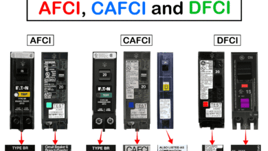 Difference Between AFCI, CAFCI, DFCI and GFCI?
-
 Can You Use a 2-Pole Breaker Instead of a 1-Pole Breaker
-
 What is the Life Expectancy of a Circuit Breaker?