Sizing Motors FLC, HP, Voltage, Breaker Size and Wire Size
How to Size Motor HP, Input Voltages, Full Load Current (FLC), Breaker Size, And Copper Wire Size for Single Phase & 3-Phase Motors
Motor load circuits are significantly different from ordinary circuits such as resistive load and lighting points. This is because motors draw 6–8 times their normal running current (known as inrush current) during startup. For this reason, three-phase motors require contactors and starters to ensure safe operation. Consequently, overcurrent protective devices (OCPDs) for motor circuits are sized differently than those for general loads. To address this, the NEC covers the requirements for motor circuits, controllers and associated calculations in a comprehensive Article 430.
The following tabulated charts provide reference values and quantities related to electric motors. In addition, solved examples and calculations are provide for both single-phase and three-phase motors.
For example, you can determine the conductor size in AWG, and breaker size in amperes for single-phase and three-phase motors. In addition, you can easily size motor circuits based on horsepower (HP) or kilowatts (kW), input rated voltage, and full-load current (FLC) in amperes.
Before proceeding, it is important to understand the difference between Full-Load Current (FLC) and Full-Load Amperes (FLA):
- FLC: A standardized current value based on motor horsepower (HP), as specified in NEC Tables 430.247 through 430.250 and in UL 508A (Table 50.1 for AC motors and Table 50.2 for DC motors).
- FLA: The actual rated current of the motor, typically printed on the motor nameplate. For this reason, the NEC refers to it as the nameplate value. In the IEC 60364 standard, the rated current (FLA) is represented as Ib, while the nameplate current is represented as IN.
FLC is used to determine the proper size of protective devices (e.g., fuses and circuit breakers) for branch-circuit conductor and short-circuit and ground-fault protection for motors, while FLA is used to determine the appropriate setting for motor overload protection.
Below are some important formulas for key quantities and terms associated with single-phase and three-phase motors.
Motor Shaft Power in kW
Shaft Power in kW = Input Power in kW × Efficiency in %
Where:
- Shaft power = Output mechanical power available at motor’s shaft.
- Input Power = Electrical input power in kW × efficiency in % or kilo-volt-amperes (kVA)
Based on the relation between input and output power:
Shaft Power of Single-Phase Motor
Motor Shaft Power (kW) = (V × A × P.F * η) ÷ 1000
Shaft Power of Three-Phase Motor
Motor Shaft Power (kW) = (√3 × V × A × P.F * η) ÷ 1000
Where
- V = Line Voltage
- A = Line Current (Rated or Full Load Current)
- P.F = Power Factor (Cos ϕ)
- ɳ = Motor efficiency
Calculation of Full Load Current
The Full-Load Current (FLC) in amperes for DC motors as well as single-phase and three-phase motors can typically be obtained directly from the NEC tables. However, in the absence of tabulated data, the FLC can also be calculated using the standard formulas for 1-phase and 3-phase motors.
Example 1 – FLC of 1-Phase Motor:
Let’s calculate the FLC of a 1.5 kW (2 HP) single-phase motor operating at 240V, with a power factor (P.F.) of 0.75 and 70% efficiency.
FLC in Amp = Power in kW × 1000 / (V × P.F × ɳ)
Lets calculate the value of FLC for 1.5kW (2HP) single phase motor operated at 240V single phase having P.F 0.75 and 70% efficiency
FLC in Amp = (1.5 × 1000) ÷ (240 × 0.75 × 0.7)
= 1,500 ÷ 126
= 11.9 Amps.
The calculated FLC is approximately 12A, which closely matches the tabulated value of FLC given in Table 1 for 1.5kW (2HP) single phase motor operated at 240V given in Table 1 for single-phase motors.
Example 2 – FLC of 3-Phase Motor:
Now, consider a 30 kW (40 HP) motor operating on a 415 V, three-phase supply, with a power factor (P.F.) of 0.8 and 80% efficiency.
FLC in Amp = Power in kW × 1000 / (√3 × V × P.F × ɳ)
For instance, let’s calculate the FLC of a 30kW (40HP) motor operated at 415V three-phase supply having P.F 0.8 and efficiency 80%.
FLC in Amp = (30 × 1000) ÷ (√3 × 415 × 0.8 × 0.8)
= 30,000 ÷ 460)
= 65.21 Amps.
The calculated FLC is approximately 66A, which is consistent with the tabulated value provided in Table 2 for 30kW (40HP) operating at 425V three-phase motors.
Required Wire Size in AWG for Motors
Now, let’s find suitable size of wire in AWG for single phase or three phase motors based on FLC.
Example:
What is the appropriate wire in AWG for a 7½ HP (5.6 kW) single phase motor operated at 240V?
Solution:
The value of full load current (FLC) for 7½ HP (5.6 kW) 1-phase motor is 40-amps (Table 1 – Based on NEC Table 430.248). NEC 430.22(A) and 430.6(A)(1) requires the branch circuit conductors must be sized at 125% of the continuous-duty motor’s full load current (FLC).
Amps = FLC × 1.25
= 40 × 1.25
= 40 × 1.25
= 50 Amps
Using the table 1 (based on NEC Table 310.16), the suitable wire size for 7½ HP (5.6 kW) single phase motor operated at 240V is #6 AWG (Cu), which has an ampacity of 55A at 60°C.
Required Wire Size of Breakers & Fuse
The protective devices for short circuit and ground fault protection is sized based on NEC Table 430.52(C)(1) in accordance with NEC Table 310.16. Let’s have a look:
Example:
What is the correct size of inverse time circuit breaker to protect a 20HP (15 kW) three phase motor operated at 460-480V?
Solution:
The full load current of 20HP (15 kW), 3-phase motor operated at 460V is 27-amp (Table 2 – based on NEC table 430.250).
Inverse Time Breaker
The size of breaker for motors shall be rated at 250% of the FLC using NEC Table 430.52(C)(1).
Cricut Braker Rating = 27A × 2.5 = 85A
= 67.5
The next standard available size of breaker is 70-amp. Hence, you can use 70-amp inverse time breaker to protect a 20HP (15 kW), 3-phase motor operated at 460V from short circuit and ground faults.
Tables
Table – 1 for Single-Phase Motors
| Single-Phase Motors HP, FLC, Voltage, Breaker Size in Amp & Wire Size in AWG | |||||||
| HP | kW | 115V – 120V | 230V – 240V | ||||
| FLC in Amp | Breaker Size (A) | Wire Size in AWG | FLC in Amp | Breaker Size (A) | Wire Size in AWG | ||
| ⅙ | 0.124 | 4.4 | 15 | 14* | 2.2 | 10 – 15* | 14* |
| ¼ | 0.186 | 5.8 | 15 | 14* | 2.9 | 10 – 15* | 14* |
| ⅓ | 0.250 | 7.2 | 20 | 14* | 3.6 | 10 – 15* | 14* |
| ½ | 0.373 | 9.8 | 25 | 14* | 4.9 | 15 | 14* |
| ¾ | 0.560 | 13.8 | 35 | 12 | 6.9 | 20 | 14* |
| 1 | 0.746 | 16 | 40 | 12 | 8.0 | 20 | 14* |
| 1½ | 1.119 | 20 | 50 | 10 | 10 | 25 | 14 |
| 2 | 1.50 | 24 | 60 | 10 | 12 | 30 | 14 |
| 3 | 2.24 | 34 | 90 | 6 | 17 | 45 | 10 |
| 5 | 3.73 | 56 | 150 | 4 | 28 | 70 | 8 |
| 7½ | 5.60 | 80 | 200 | 1 | 40 | 100 | 6 |
| 10 | 7.46 | 100 | 250 | 1/0** | 50 | 125 | 4 |
|
|||||||
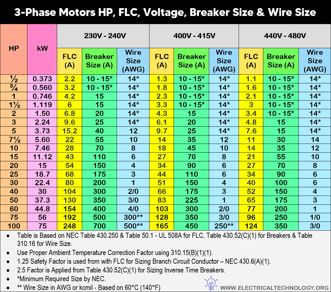
Table – 2 for Three-Phase Motors
| Three-Phase Motors HP, FLC, Voltage, Breaker Size in Amp & Wire Size in AWG | ||||||||||
| HP | kW | 230V – 240V | 400V – 415V | 440V – 480V | ||||||
| FLC (A) | Breaker Size (A) | Wire Size (AWG) | FLC (A) | Breaker Size (A) | Wire Size (AWG) | FLC (A) | Breaker Size (A) | Wire Size (AWG) | ||
| ½ | 0.373 | 2.2 | 10 – 15* | 14* | 1.3 | 10 – 15* | 14* | 1.1 | 10 – 15* | 14* |
| ¾ | 0.560 | 3.2 | 10 – 15* | 14* | 1.8 | 10 – 15* | 14* | 1.6 | 10 – 15* | 14* |
| 1 | 0.746 | 4.2 | 15 | 14* | 2.3 | 10 – 15* | 14* | 2.1 | 10 – 15* | 14* |
| 1½ | 1.119 | 6 | 15 | 14* | 3.3 | 10 – 15* | 14* | 3 | 10 – 15* | 14* |
| 2 | 1.50 | 6.8 | 20 | 14* | 4.3 | 15 | 14* | 3.4 | 10 – 15* | 14* |
| 3 | 2.24 | 9.6 | 25 | 14* | 6.1 | 20 | 14* | 4.8 | 15 | 14* |
| 5 | 3.73 | 15.2 | 40 | 12 | 9.7 | 25 | 14* | 7.6 | 15 | 14* |
| 7½ | 5.60 | 22 | 55 | 10 | 14 | 35 | 12 | 11 | 30 | 14 |
| 10 | 7.46 | 28 | 70 | 8 | 18 | 45 | 10 | 14 | 35 | 12 |
| 15 | 11.12 | 43 | 110 | 6 | 27 | 70 | 8 | 21 | 55 | 10 |
| 20 | 15 | 54 | 150 | 4 | 34 | 90 | 6 | 27 | 70 | 8 |
| 25 | 18.7 | 68 | 175 | 3 | 44 | 110 | 6 | 34 | 90 | 6 |
| 30 | 22.4 | 80 | 200 | 1 | 51 | 150 | 4 | 40 | 100 | 6 |
| 40 | 30 | 104 | 300 | 2/0 | 66 | 175 | 3 | 52 | 150 | 4 |
| 50 | 37.3 | 130 | 350 | 3/0 | 83 | 225 | 1 | 65 | 175 | 3 |
| 60 | 44.8 | 154 | 400 | 4/0 | 103 | 300 | 2/0 | 77 | 200 | 1 |
| 75 | 56 | 192 | 500 | 300** | 128 | 350 | 3/0 | 96 | 250 | 1/0 |
| 100 | 75 | 248 | 700 | 500** | 165 | 450 | 250** | 124 | 350 | 3/0 |
|
||||||||||
If you would like to download them, the tables below are provided in image format for reference.
Table 1 – Click image or open in a new tab to enlarge

Table 2 – Click image or open in a new tab to enlarge
Related Motor Circuit Calculations
- Part 1 – Motor Load Circuits: NEC Terms and Basic Terminologies
- Part 2 – NEC Requirements for Motor Circuits
- Part 3 – Understanding NEMA Motor Nameplate Data
- Part 4 – Calculating Locked Rotor Current (LRC) for Motors
- Part 5 – Sizing Motor Branch Circuit Conductors
- Part 6 – Sizing Motor Feeder Conductors
- Part 7 – Sizing Motor Overcurrent Protection and OCPD’s Devices
- Part 8 – Sizing Motor Feeder Protection
- Part 9 – Sizing Motor Overload Protection
- Part 10 – Overcurrent Protection for Motor Control Circuits
- Part 11 – Sizing Disconnecting Means for Motor & Controller
- Part 12 – Sizing Motor Starter & Contactor – NEMA – NEC
- Part 13 – Sizing Direct Online (DOL) Starters/Contactors for Motors (*Bonus)
- Part 14 – Sizing Star-Delta Motor Starters/Contactors for Motors (*Bonus)
Resources & Tutorials:
- Cable Size Calculation for LT & HT Motors
- Three Phase Motor Power & Control Wiring Diagrams
- What is Motor Efficiency & How to improve it?
- Star Delta 3-phase Motor Automatic starter with Timer
- How to Run a Three-Phase Induction Motor on a Single-Phase Power Supply?
- How to Wire ST01 Timer with Relay & Contactor for 120V/240V Motors?
- How to Wire Twin Timer in Repeat Cycle & One-Shot Mode for 120V/240V Motors?
- How to Control a Single-Phase Motor from Multiple Locations?
- Automatic & Manual Control of Motor Using VFD & DOL Starter
- How to Reverse and Forward a Three-Phase Motor Using a VFD?
- How to Wire a VFD with Motor, PLC, Switches & External Devices
- Sequential Motor Control Circuit Using LOGO! V8 PLC
- Automatic Reverse Forward Motor Control Circuit Using Delta – DVP-14SS PLC
- Reverse Forward Motor Control Circuit Using PLC – ZEN Programming Relay
- Motor Protection – Types of Faults and Protection Devices
Wire Sizing Guides
- How to Find the Proper Size of Wire & Cable In Metric & Imperial Systems
- How Size a Circuit Breaker for Different Load Applications
- How to Size a Branch Circuit Conductors with Protection?
- How to Size a Load Center, Panelboards and Distribution Board?
- How to Determine the Right Size Capacity of a Subpanel?
- How to Size Feeder Conductors with Overcurrent Protection
- How to Size Service-Entrance Conductors and Feeder Cables?
- How to Size Equipment Grounding Conductor (EGC)?
- How to Size Grounding Electrode Conductor (GEC)?
- How to Size Earth Conductor, Earthing Lead and Earth Electrodes?
- What is the Right Wire Size for 15A Breaker and Outlet?
- What is the Suitable Wire Size for 20A Breaker and Outlet?
- What is the Correct Wire Size for 100A Breaker and Load?
- How to Find the Right Wire Size for 100A Service 120V/240V Panel?


what is difference between the kiolowatt(megawatt) and horse power(hp) of motor???
both are same.. also, 1hp = 746Watts.
Above 7.5HP motors may up-to 400Hp What would be the cable size(in sqmm), full load current and CB, pls give the easiest calculation..
Above 7.5HP motors may up-to 400Hp What would be the cable size(in sqmm), full load current and CB, pls give the easiest calculation..
In the 3-phase motor the supplied voltage will be 400V or 230V?
Wait to update the full chart…
Where could we find this information in the codebook for ourselves?