How to Wire a Smart Wireless Switch and Anywhere Companion
Wiring a Smart Wireless Switch and Wire-Free Smart Switch Anywhere Companion
In the smart devices wiring series, we take a step further into advanced automation with hassle-free installation i.e. installation of wireless smart switch and wire-free smart anywhere companion devices for multi-way switching control.
In this wiring tutorial, we will show the installation tutorial of wire-free smart switch companion devices, as well as the wireless smart switch with Netatmo for 3-way, 4-way or multi-way control of the connected load point.
Wireless Smart Switches
Wireless Smart Switch with Netatmo – By Legrand
The Legrand radiant wireless smart switch with Netatmo (WNRL23WH) is a battery-powered wire-free switch. It is designed to provide flexible multi-location smart lighting control without the need for additional wiring. Instead of directly switching the electrical load, it wirelessly pairs with a compatible radiant smart switch, dimmer, or plug-in device. It allows you to add convenient control points anywhere in the room.
The wireless smart switch is an Ideal for retrofits or spaces without traveler wiring. It mounts easily using adhesive (double sided stickers) or screws and operates over a dedicated Netatmo mesh network. In short, it is used to control the same light from an additional location which is a perfect choice for smart home automation.
Click image or open in a new tab to enlarge
Wire-Free Smart Swathes Anywhere Companion – By Leviton
The Leviton smart switch anywhere companion (DAWSC) are battery powered and totally wire-free smart control devices. These are designed to add convenient ON/OFF switching locations without the need for additional wiring.
Smart anywhere switch companion pairs wirelessly with compatible Decora® Smart Wi-Fi switches, dimmers, or plug-in devices to create multi-way (3-way, 4-way, or more) control points in areas where running traveler wires is impractical or impossible.
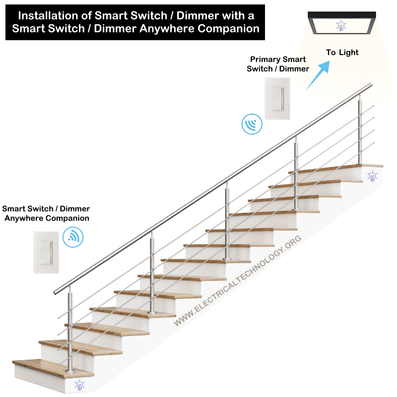
These switches mounts directly on the wall or existing wall box. While it can’t be used to control a direct load point, instead, it can be used with other smart devices to control the same load points from additional location. Thus, it is a suitable choice for basement, staircase and hallways to provides a simple and efficient solution for expanding lighting control anywhere in residential installations.
Wiring a Smart Wireless Switch
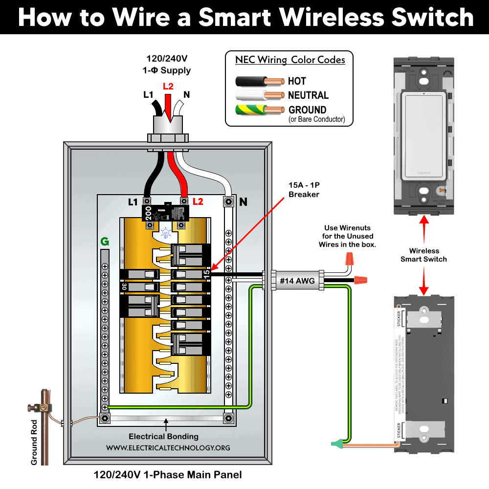
A wireless smart switch in the Legrand radiant with Netatmo system is fundamentally different from a conventional wired switch. It is battery-powered and communicates wirelessly. This way, it does not require line, load, or traveler conductors, but only ground wire. Instead, it must be paired with a wired smart switch or gateway that actually controls the load.
This warless smart switch replaces traditional 3-way or multi-way switching with a low-power RF mesh network. Hence, it can be used without extra wires as an additional ON/OFF control point for smart dimmer, switches and outlets.
To wire a smart wireless switch:
- Even though the wireless switch itself has no line voltage wiring, turn OFF the breaker if installing near an existing electrical box. This safety precaution ensure safe handling of any exposed conductors.
- Choose a location near an existing switch or any convenient wall position. Align the device with existing switches for proper aesthetics. If mounting near a box, ensure wires inside are neatly folded.
- If installed over a metal box, connect the ground wire to the box grounding conductor using a wire connector. This is only for grounding continuity, not for operation.
- Mount the wireless smart switch as follow:
- Adhesive Mounting: Remove the backing from the double-sided adhesive. Stick the device directly onto a smooth wall surface.
- Screw Mounting: Use screws if surface is uneven, mounting to drywall or electrical box. Install subframe (if provided), then snap on the wall plate.
- Remove the battery insulation tab to activate the switch. The device is powered by a long-lasting internal 3V battery.
Click image or open in a new tab to enlarge
Pairing & Testing the Wireless Switch
Pair the wireless switch with a wired smart switch, and the Netatmo Smart Gateway. For this purpose, use the Home + Control app by Legrand for pairing.
Press and hold the switch button. Wait for LED indication (blinking indicates steady) and confirm pairing with the system.
Connect the primary smart device to the home network by following the on screen instruction in the app.
To test the smart warless switch:
Press the wireless switch. The paired light or load should turn ON/OFF. Verify operation from multiple locations in multi-way control.
The EZ button on the device is used to initiate the the switch in setup mode. The status LED indicates the current state of the device during setup in the network. When the status LED flashes Green, it indicates the device is ready and attempting to pair to the network.
To delete a device from the network or reset to the factory default, press and hold the EZ button for 15 seconds until the LED blinks Green and Red. Release the button and the LED will turn OFF. It means all the paired devices are unpaired now.
Wiring a Wire-Free Smart Switch Anywhere Companion
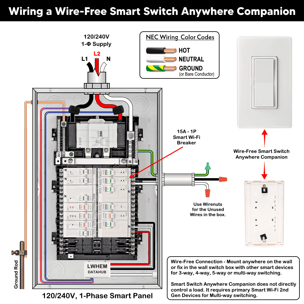
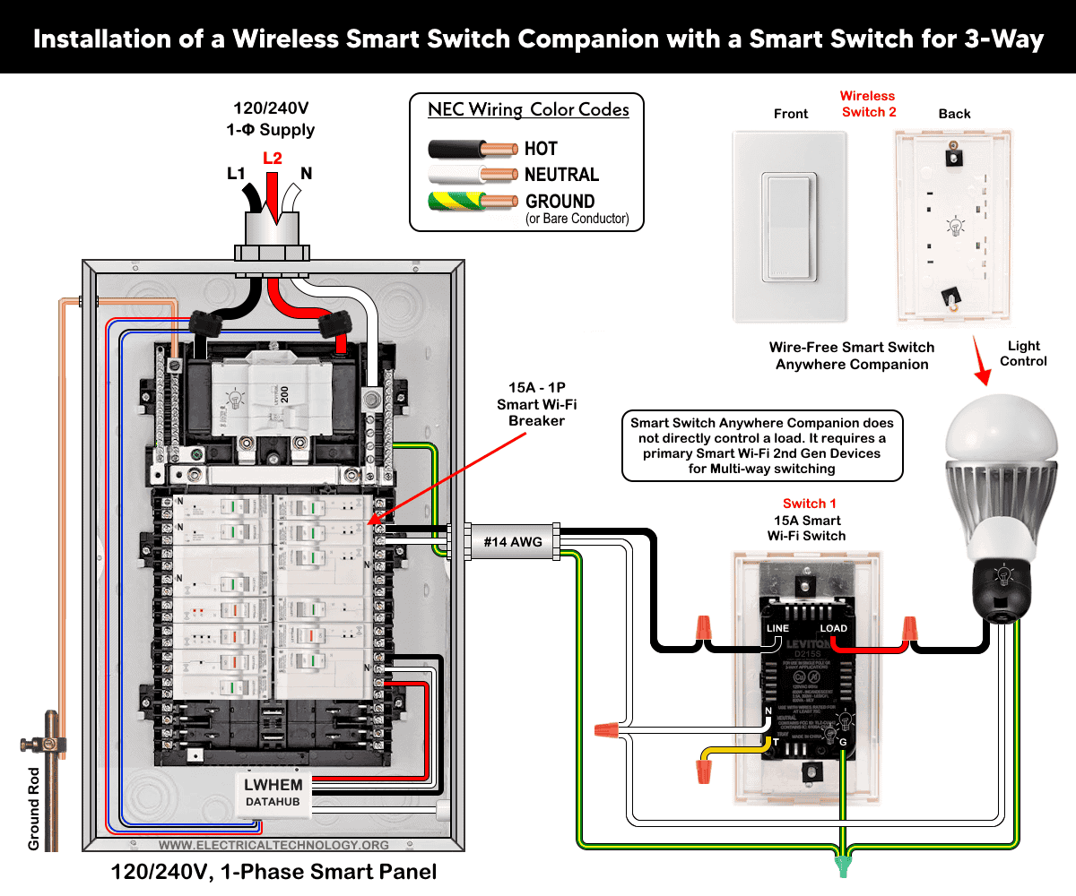
A Wire-Free anywhere companion switch by Leviton is not wired in the traditional electrical sense. It is a battery-powered wireless control device that communicates with a wired Decora® Smart switch or plug, which actually controls the load (light or appliance).
Smart anywhere companion switch replaces traditional 3-way traveler wiring with a wireless control topology, where primary device is a power switching node and the anywhere companion acts as a control interface node.
Click image or open in a new tab to enlarge
Before installation, make sure a compatible primary device (list given above) is already installed.
Here is how to wire a wire-free smart switch anywhere companion device:
- Even though no wiring is involved, turn OFF the breaker if installing over an existing wall box to prevent accidental contact with live conductors.
- Choose a location within 50 ft (15 m) of the primary smart device such as staircases, hallways, multi-entry rooms etc.
- Mount the companion switch as follow:
- Surface Mount: Apply the adhesive tape on the back of the device. Align using molded corner guides. Press firmly onto the wall surface
- Mount on Wall Box: Align the switch with screw holes of the wall box. Ensure correct orientation (TOP marking). Secure using mounting screws. In this method, no wires are connected inside the box i.e. it is purely mechanical mounting.
- Remove the battery tab to activate the switch. It uses two replaceable long life coin-cell battery (2 x CR2025).
Click image or open in a new tab to enlarge
Pairing with Smart Device, Powering & Testing
The primary smart device will automatically pair with the Anywhere Switch Companion when the Companion is in pairing mode and within wireless RF range. Once paired, the Anywhere Switch Companion’s status LED will briefly light up solid green to confirm a successful connection.
The companion must be linked to a Decora® Smart switch, dimmer, or plug. To pair:
- After removing both pull tabs for each battery, press and hold the companion switch button. The status LED will flash Green which indicates it is ready to pair.
- Follow pairing steps on the primary smart device using My Leviton app.
No Wi-Fi is required for basic pairing in many setups. The status LED shows paring, connectivity and OFF during normal operation.
To test the operation, press:
-
- Top rocker: ON
- Bottom rocker: OFF
Verify that the connected load responds correctly as per requirement. During operation, the status LED on the device Indicates:
- Green or No light: Normal operation
- Amber: Not connected to any smart device
- Red: Low battery
To rest to the factory default, press the top rocker for 14 seconds. The LED will flash amber and then quickly flash red. Release the rocker and the switch is restore to the factory default which means all the paired devices are unpaired.
Performance may degrade in metal boxes or metal wall plates due to RF shielding.
By using the smart switch anywhere companion device, it effectively converts a conventional hardwired multi-way switching circuit into a distributed wireless control system.
Hence, it reduces wiring complexity, installation cost and retrofit constraints.
Instructions & Precautions
- Make sure to disconnect the power supply by switching OFF the breaker in the main panel before doing any electrical work.
- The wire length from smart switch to other companion device should not exceed 300 ft (90 meters).
- Smart devices are only suitable for indoor use, and should not be used for medical applications.
Disclaimer:
- The author will not be liable for any losses, injuries, or damages from the display or use of this information or if you try any circuit in wrong format. So please! Be careful because it’s all about electricity and electricity is too dangerous. If you are unsure, contact a licensed electrician to do it according to the local area codes.
Resources:
Smart Devices Wiring Series
- How to Wire a Smart Switch in a 120/240V Load Center
- How to Wire 120/240V Smart Load Center with Smart Breakers
- How to Wire a Smart Breaker in a Smart 120/240V Panel
- How to Wire a Smart GFCI Breaker in a 120/240V Smart Panel
- How to Wire Smart AFCI/GFCI Breaker in a Smart Load Center
- How to Wire a 15A Wi-Fi Smart Outlet in a Smart Panel
- How to Wire 15A and 20A Wi-Fi Smart GFCI Outlets
- How to Wire Z-Wave Smart Switch, Dimmer & Fan Speed Controller
- How to Wire a Digital and Wi-Fi Smart LED Dimmer Switch
- How to Wire a Smart Switch Companion with a Smart Switch
- Wiring a Smart Dimmer Switch Companion with a Digital Dimmer
- How to Install a Wire-Free Smart Dimmer Anywhere Companion
Wiring Standard GFCI & Breakers
- How to Wire a 1-Pole Breaker
- How to Wire a 2-Pole Breaker
- How to Wire a 3-Pole Breaker
- How to Wire a 1-Pole GFCI
- How to Wire a 2-Pole GFCI
- How to Wire a 3-Phase, 3-Pole GFCI
- How to Wire a Tandem Breaker
- How to Wire GFCI Circuit Breakers
- How to Wire an AFCI Breaker
Wiring General Outlets & GFCI/AFCI Receptacles
- How to Wire an Outlet Receptacle? Socket Outlet Wiring Diagrams
- How to wire a GFCI Outlet?
- How to Wire an AFCI Outlet?
- How to a Wire 3-Way Combination Switch and Grounded Outlet?
- How to Wire a 15A – 125V Outlet – NEMA 5-15 Receptacle
- How to Wire a 20A – 125V Outlet – NEMA 5-20 Receptacle
- How to Wire a 15A – 250V Outlet – NEMA 6-15 Receptacle
- How to Wire a 20A – 250V Outlet – NEMA 6-20 Receptacle
- How to Wire a 50A – 125/250V Outlet – NEMA 14-50 Receptacle
Switches Wiring
- How to Wire Single Pole, Single Throw (SPST) as 2-Way Switch?
- How to Wire Single Pole, Double Throw (SPDT) as 3-Way Switch?
- How to Wire Double Pole, Single Throw Switch? Wiring DPST
- How to Wire Double Pole, Double Throw Switch? Wiring DPDT
- How to Wire Double Switch? 2-Gang, 1-Way Switch – IEC & NEC
- How to Wire 4-Way Switch (NEC) or Intermediate Switch as 3-Way (IEC)?
- How to Wire Auto & Manual Changeover & Transfer Switch – (1 & 3 Phase)
Sizing Breakers, Wires & Panels
- How to Size a Load Center, Panelboards and Distribution Board?
- How to Determine the Right Size Capacity of a Subpanel?
- How to Find the Right Wire Size for 100A Service 120V/240V Panel?
- How to Size a Circuit Breaker?
- How to Find the Proper Size of Wire & Cable In Metric & Imperial Systems
- How to Size a Breaker and Wires in AWG with EGC for Load?
- How to Size Service-Entrance Conductors and Feeder Cables?
- How to Size Feeder Conductors with Overcurrent Protection
- How to Size a Branch Circuit Conductors with Protection?
- How to Size Equipment Grounding Conductor (EGC)?
- How to Size Grounding Electrode Conductor (GEC)?
- How to Size Main Bonding Jumper (MBJ)?
- How to Size Motors FLC, HP, Voltage, Breaker Size and Wire Size
- What is the Correct Wire Size for 100A Breaker and Load?
- What is the Right Wire Size for 15A Breaker and Outlet?
- What is the Suitable Wire Size for 20A Breaker and Outlet?
Finding the Number of Breakers/Outlets in a Circuit
- How to Determine the Number of Circuit Breakers in a Panelboard?
- How to Find the Number of Outlets on a Single Circuit Breaker?
- How to Find Voltage & Ampere Rating of Switch, Plug, Outlet & Receptacle
- How to Calculate the Number of Fluorescent Lamps in a Final Sub Circuit?
- How to Calculate the Number of Incandescent Lamps in a Final Sub Circuit?
- How to Determine the Number of Lighting Branch Circuits?
- How to Determine the Number of Branch Circuits? – 3 Ways
- How to Find the Number of Lights on a Single Circuit Breaker?