Electronic Relay Switch Circuit – NPN, PNP, N & P Channel Relay Switches
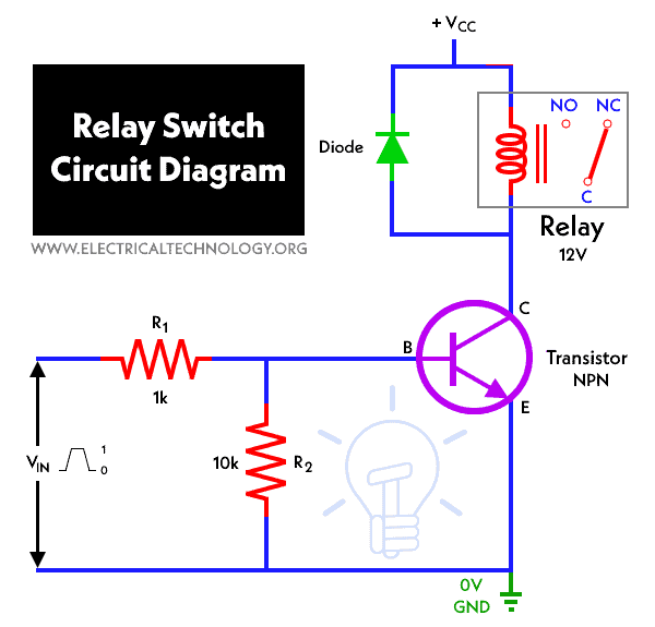
Electronic Relay Switch Circuit Diagram and Its Working
There are a variety of electrical and electronic devices which are classified as Output devices such devices are used to control or operate some external physical process of a machine or device. These output devices are commonly called Actuators.
These actuators convert the electrical energy into physical unit called force, speed etc. A relay is basically a binary actuator with two stable states. In this article, we will be discussing the details of relay switch circuit, it designs and features.
Click image to enlarge
What are Electrical Relays?
These are electrically operated switches that come in various shapes, sizes and power ratings. Electrical relays are suitable for almost every type of applications. Relays can have single or multiple contacts within a single package. The larger power relays are mainly used for mains voltage or high current switching applications called “Contactors”. Let us see the classifications of Relay.
- Related Post: Electronic Circuit Breaker – Schematic and Working
The electrical relays are basically divided into two subcategories namely:
Electromechanical Relays:
As the name suggests, electromechanical relays are electro-magnetic devices. Basically it convert a magnetic flux generated by the application of an electrical control signal into a pulling mechanical force which operates the electrical contacts within the relay switch. The simplest and most common form of electrochemical relays is made up of energizing coil wound around a permeable iron core. This energizing coil is also called primary circuit.
Electrochemical relays are used in general electrical and electronic control or switching circuits. These are either mounted directly onto PCB boards or connected as free standing. In free standing configuration, the load currents are normally functioning of an ampere.
- Related Post: Difference Between Relay and Circuit Breaker
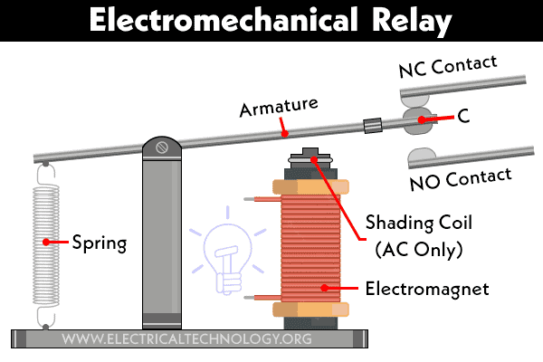
Construction of Electromechanical Relay
Relays are configured in two modes namely “Normally Open”, or “Normally Closed”. One pair of contacts is called Normally Open (NO) or make contacts and another set which are called Normally Closed (NC) or break contacts.
Now, in the normally “open” position, the contacts are closed only when the field current is “ON”. In normally “ON” position the switch contacts are pulled towards the inductive coil. One of the more important parts of any electrical relay is the coil. This coil converts electrical current into an electromagnetic flux. These magnetic fluxes are used to mechanically operate the relays contacts. The biggest problem with relay coils is that they are “highly inductive loads”. The relay coil is generally made from coils of wire.
As the current flows through the coil, the self-induced magnetic field is generated around it. When the current is turned “OFF” in the coil, a large back emf voltage is produced. This is due to collision of magnetic flux with the coil. The induced reverse voltage value is very high as compared to the switching voltage. This voltage is capable enough to damage any semiconductor device such as a transistor, FET or micro-controller used to operate the relay.
Note: These terms “Normally Open” and “Normally Closed “or Make and Break Contacts refer to the state of the electrical contacts when the relay coil is “de-energized”, i.e., no supply voltage connected to the relay coil.
One important point to remember about using electrical relays is that “It is not advisable to connect relay contacts in parallel to handle higher load currents”. Ex- Never attempt to supply a 10A load with two relay contacts in parallel that have 5A contact ratings each.
Relay contacts are constructed using conductive pieces which allows the current to pass through them when comes in contact. They are designed just like a switch. As soon as the contacts are open, the resistance between the contacts becomes very high. This results in an open circuit condition and no circuit current flows through the relay.
After some time, the moving parts of electrochemical relay will wear out and fail or the constant arcing and erosion may make the relay unusable. Also, they are electrically noisy with the contacts suffering from contact bounce that might affect the electrical circuit to which they are connected. To overcome the difficulty of this relay, another type of relay called solid state relay was developed.
Solid State Relay:
The solid-state relay has no moving parts. It is a purely electronic device There are no moving parts in this relay type because the mechanical contacts are replaced by power transistors, thyristors or triac’s.
Absence of any movable part makes the relay highly reliable, long lasting and reduced electromagnetic interference. This makes the solid-state relay much faster and accurate, as compared to the conventional electromechanical relay. The input power requirements of the solid-state relay for control are generally low enough to make them compatible with most IC families.
As the output switching device of a solid-state relay is a semiconductor device, the voltage drops across the output terminals of an SSR when “ON” is much higher as compared to that of the electromechanical relay. Typically, it is between1.5 – 2.0 volts. An additional heat sink will be required to switch large currents for long period of time.
You can use them without the need for of adding drivers or amplifiers. However, they must be mounted onto suitable heatsinks plate or material to prevent the output switching semiconductor device from overheating as it is a semiconductor device. The design and type of relay switching circuit is quite huge. A relay is said to switch one or more poles just like a simple switch circuit. Each pole of relay has contacts that can be thrown in three different ways:
- Related Post: How to Test a Relay? Checking SSR & Coil Relays
Different ways in which relay can be thrown:
- Normally Open Contact (NO): This is also called a make contact. This contact will close the circuit when the relay is activated. It disconnects the circuit when the relay is in inactive state.
- Normally Closed Contact (NC): This is known as break contact. The function is opposite to that of the NO contact. When the relay is activated, the circuit disconnected in result. When the relay is deactivated, the circuit start to connect.
- Change-over (CO) / Double-throw (DT) Contacts: They are used to control a NO contact and a NC contact with a common terminal. That means, they are used to control two types of circuit. According to their type they are called “break before make” and “make before break” contacts name.
Important:
Relays are designed for two basic operations. One is for low voltage application and the other is for high voltage. For low voltage applications, relay is designed to reduce the noise of the whole circuit. For high voltage applications, they are mainly designed to reduce the arcing phenomenon
Some of the common ways of switching relays:
Input output interface module relay:I/O Modules) are another type of solid-state relay, designed specifically to interface devices like computers, micro-controller or PIC’s to loads and switches. There are basically four types of I/O modules available in the market.
These are AC or DC Input voltage to TTL or CMOS logic level output, and TTL or CMOS logic input to an AC or DC Output voltage. Each of the modules contains all the necessary circuitry to provide a complete interface and isolation within one device. They are available as individual solid-state modules or integrated into 4, 8 or 16 channel devices in the market.
- Related Post: Relay Symbols – Electrical and Electronic Symbols
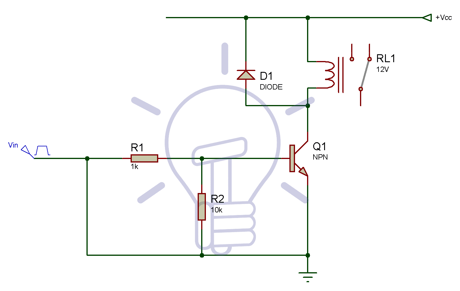
NPN Relay Switch Circuit:
A typical NPN relay switch circuit has the coil driven by a NPN transistor switch. When the Base voltage of the transistor is zero, the transistor will be in cut-off region and acts as an open switch. In this situation, no Collector current flows and the relay coil is de-energised.
If there is no current flowing into the Base, then no current will flow through the relay coil as well. If a large positive current is now driven into the Base to saturate region of the NPN transistor, the current starts flowing from Base to Emitter.
PNP Relay Switch Circuit:
The PNP relay switch circuit needs different polarity of operating voltage. It’s similar to NPN relay switching circuit in terms of its ability to control the relays coil. For example, the Collector-Emitter voltage must be negative for the PNP type to make current flow from the Emitter to Collector.

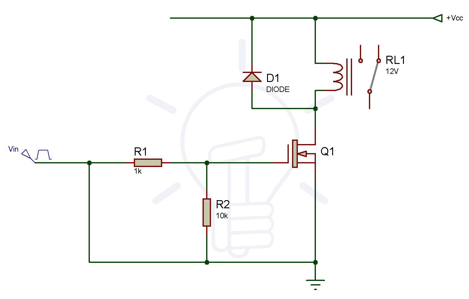
N-Channel Relay Switches Circuit:
MOSFET relay switching operation is quite like Bipolar Junction Transistor (BJT) switch operation. The main difference between operations is that MOSFETs are voltage operated devices. However, the Gate is electrically isolated from the Drain-Source channel. N-channel Enhancement MOSFETs are the most commonly used type of MOSFET. A positive voltage on the Gate terminal switches the MOSFET “ON” and a negative voltage on the Gate make it “OFF”. This makes it ideal for MOSFET relay switch.
P-Channel Relay Switches Circuit:
Unlike the N-channel Enhancement MOSFET, it operates with negative Gate voltages only. In this configuration, the source terminal of P-channel is connected to +Vdd and the Drain terminal is connected to the ground. Both are connected via the relays coil. When a HIGH voltage level is applied to the Gate terminal, then the P-channel MOSFET will be turned “OFF” consequently.

Points to keep in mind while choosing a suitable relay:
- Make sure that they are they have good coil protection and contact protection
- Look for standard relays with regulatory approvals
- Go for high speed switching relays
- Wisely choose for the type of contacts
- Make sure there is isolation between the coil circuit and contacts in your relay
Let’s understand the working of relay circuit with an example:
Suppose, you have need to turn ON a CFL bulb using a relay switch. In this relay circuit, we are using a push button to trigger a 5V relay, which in turn, complete the second circuit and turn on the lamp.
Gather the following components to design the circuit:
- Relay 5V
- Bulb Holder
- CFL
- Push ON/OFF Button
- Perf-Board
- 9V battery
- AC supply
A typical ON/OFF switch is added for the switching purpose of the relay device. In the above circuit, the 5V relay is powered by a 9V battery. Initially when the switch is open, no current will flow through coil. In result, Common Port of relay is connected to “NO” (Normally Open) contact. Therefore, the LAMP will remain “OFF”.
When the switch is closed, current will start flowing through the coil. Here, the magnetic field is generated in the coil which attracts the movable armature due to electromagnetic induction and the Com Port gets connected with NC (Normally Close) contact of the relay. In result, the CFL will turn “ON”.
The main disadvantages of solid-state relays as compared to that of an equivalent wattage electromechanical relay are their higher costs. Only single pole single throw types are available, “OFF”-state leakage currents flow through the switching device, and a high “ON”-state voltage drop and power dissipation results in additional heat sinking requirements. Also, the typical sold state relays can’t switch very small load currents or high frequency signals such as audio or video signal. However, special Solid-State Switches are available for this type of applications.
Both electrochemical relay as well as the solid-state relay is of great importance in day to day life. You can choose any of them depending on your requirement in the device. Solid state relays come with a rather large and perhaps intimidating upfront price tag as compared to electromechanical relays.
However, the movement of this solid-state relay contact is generated using electromagnetic forces from the low-power input signal. This allows the completion of the circuit that contains the high-power signal. Hence, the solid-state relays are superior to electromechanical ones. The Electromechanical relays are of relatively old technology that uses a simple mechanical design approach.
Applications:
There are a wide range of relay applications. Some of the most common applications are:
- Relay circuit can used to realize logic functions
- They also provide safety critical logic
- Relays can be used to provide time delay functions
- They are used to control high current circuits with the help of low current signals
In this article, we have discussed the different types of relays, their working and its applications. Now, you have got a good knowledge of relays and its functions. After reading this article, you will be able to design a relay on your own without any inconvenience.
Related Electronic Projects Circuits:
- Difference Between Solid-State Relay and Electromechanical Relay
- PNP Transistor
- NPN Transistor
- Automatic Bathroom Light Switch Circuit Diagram and Operation
- Car Speed Detector Circuit – Working and Source Code
- Smart Home Automation System – Circuit and Source Code
- Simple Touch Sensitive Switch Circuit using 555 Timer & BC547 Transistor
- LED Roulette Circuit Diagram using 555 Timer & 4017 Counter


Thank you for the nice information
Those are JFET par numbers and symbols in the schematics, not MOSFETs.
We have updated the symbols. Thanks for correction.
Mst item h re baba. Kya system bnaya h re.