Voltage Source: Types of Dependent & Independent Voltage Sources
What is Voltage Source? Different Types of Voltage Sources
Modern-day equipment & gadgets require electrical power to operate. We cannot imagine our life without electricity. Various kinds of sources are used to provide electrical power to meet the needs of consumers. They are collectively termed electrical sources.
An electrical source is a device that provides electrical power to the connected load. It converts any other form of energy such as heat, light, wind, nuclear, mechanical, or chemical energy into electrical energy. It provides electrical energy to run the connected electrical load. Examples of electrical sources are the battery (converts chemical energy), generator (converts mechanical energy), solar panels (converts solar or light energy), wind turbines (converts wind energy), etc.
An electrical source is classified into two main types
- Voltage Source
- Current Source
In this article, we are going to discuss voltage sources and their types.
What is Voltage Source?
A voltage source is an electrical source that provides constant voltage irrespective of the current being drawn from it. In other words, it provides the force behind the movement of the electrons in the connected circuit. It has two terminals that has constant potential difference between them independent of the connected load.
Related Posts:
- What is Current Source? Different Types of Current Sources
- Difference Between Voltage Source and Current Source
Types of Voltage Sources
The voltage source can be classified into two types
- Independent Voltage Source
- Dependent Voltage Source
Independent Voltage Source
An independent voltage source provides a constant voltage that is not dependent on the other variables in the circuit. The term ‘independent source’ means the potential difference between its terminal is independent & remains constant in all circumstances. It is symbolically denoted by a circular symbol.
An independent source can be categorized into two types
- Direct Voltage Source
- Alternating Voltage Source
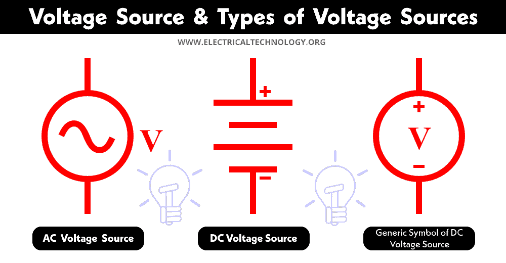
Direct Voltage Source
A direct voltage source or DC voltage source is a type of voltage source that provides a constant voltage that does not vary with time. It has defined polarities as positive ‘+’ & negative ‘-‘. Where the current or electrons flow in one fixed direction determined by the polarity of the voltage source.

A DC voltage source can be represented in either two representations i.e. it has a positive ‘+’ & negative ‘-‘ sign encircled where the signs represent the terminals of the source. It can also be represented with bars. The longer bar represents the positive while the shorter bar represents the negative terminal of the voltage source.
The electrons flow from the negative terminal to the positive terminal termed as ‘electron current’ while the conventional current is considered as the flow from the positive terminal to the negative terminal of the source.
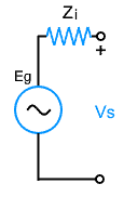
The DC source has some internal resistance that opposes the current flow when connected with a load. The equivalent circuit of a DC source with internal resistance Ri is given below.

The internal resistance Ri is in series with the emf generated Eg.
Examples of DC voltage sources are batteries, solar panels, cells, DC generators, etc.
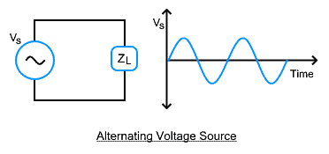
Alternating Voltage Source
The alternating voltage source or AC voltage source is a type of voltage source whose voltage is not constant but periodically varies with time. The voltage swings between its positive and negative peak value about its mean point forming a sinusoidal waveform.
The voltage polarity reverses at a fixed interval forming two halves of the waveform. Therefore the direction of the current flow also reverses in each half cycle. If a load Zl is connected with an alternating voltage source, the current I flowing through the load changes direction periodically.
The alternating voltage source also has some internal resistance that is in series with the generated emf as shown in the figure below.
Examples of alternating current sources are AC generators or alternators, inverters, etc.
Related Posts:
- What is Voltage? its Unit, Formula, Types & Applications
- What is Electric Current, its Unit, Formula, Types & Applications
Dependent Voltage Source
A dependent voltage source or controlled voltage source provides a voltage that is not constant but depends on other variables in the circuit. The voltage difference between its terminals depends on either voltage or current in other parts of the circuit. Symbolically, it is represented by a diamond shape.
The dependent voltage source can be classified into a voltage-controlled & current-controlled voltage source.
Voltage Controlled Voltage Source
Voltage controlled voltage source or VCVS is a type of dependent source whose voltage is not fixed but depends on the voltage of other components in the connected circuit. It has four terminals. Here is the symbol for VCVS where the dependent source is visualized by a diamond shape.

Here is a very simple and basic example to better understand how a voltage-controlled voltage source works.

There are two voltage sources Vin & Vout where the Vin is an independent voltage source while the Vout is a dependent voltage source. There is an electrical circuit between them that is represented by a single resistor R. The output voltage source along with the circuit is known as voltage controlled voltage source. The voltage Vr across the resistor actually controls the Vin & the controlled voltage appears as Vout. The Vout is given by ‘μVr’ where the ‘μ’ is a unit less constant also known as voltage transfer ratio.
Examples
An example of VCVS is a potentiometer used to vary an independent voltage source by varying the voltage across its terminals. By rotating the knob, its resistance varies that also varies the voltage drop across it & consequently provides a controlled voltage across it.
Another example of VCVS is an operational amplifier. In either configuration inverting or non-inverting configuration, its output voltage is controlled by varying the resistance of the resistors connected with it.
Related Posts:
- What is Electrical Power? Types of Electric Power and their Units
- What is Resistance? Resistivity (ρ) & Specific Resistance Ω.
Current Controlled Voltage Source
Current controlled voltage source or CCVS is a type of dependent source whose voltage depends on the current flowing through another component in the connected circuit. It has four terminals as shown in the figure below. The dependent source is visualized by a diamond shape.
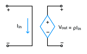
Here is a simple circuit to understand a CCVS

There are two different voltage sources; an independent voltage source Vin & a dependent voltage source Vout. The voltage of the dependent source depends on the current I through the resistor. The current varies by varying the resistance in the circuit which also vary the output voltage. Ideally, the output voltage is current ‘I’ times a multiplying constant ‘ρ’. The ρ (rho) is the ratio between the output voltage & input current, thus it is known as trans-resistance & its unit is Volts/Ampere.
Ideal Voltage Source
An ideal voltage source provides a constant voltage irrespective of the load. Its internal resistance is zero as there is no voltage drop when it delivers current. It is an independent source with zero internal resistance.
It provides a steady voltage that does not vary with change in the load forming a straight line as shown in the figure below.

As there is zero internal resistance, there is no voltage drop inside the source, thus all of the voltage appears at the load making it the most efficient voltage source. But it is not possible in the real world as there is always some internal resistance.
Characteristics of Ideal Voltage Source
- It offers a constant voltage irrespective of the load current.
- It has zero internal resistance, therefore there is no internal voltage drop.
Suppose if we short-circuit the two terminals of an ideal voltage source, there should be no potential difference across it as there is no internal resistance. However, an ideal voltage source’s voltage remains constant. The statements contradict each other. Therefore ideal voltage source does not exist in the real world but they are considered for circuit analysis.
Related Posts:
- What is Electricity? Types, Sources & Generation of Electricity
- What is Electrical Energy? Its Unit, Formula & Applications
Practical Voltage Source
A practical or real voltage source provides voltage across its terminal that reduces the amount of current being drawn from it. It has some internal resistance in series with the emf Vg generated. With the increase in the current I, the voltage drop across the internal resistance increases which reduces the voltage drop across the source terminals. The graph of voltage with respect to load shows reducing voltage with an increase in load.

Characteristics of Practical Voltage Source
Here are some characteristics of a practical voltage source.
- Its voltage depends on the amount of current being drawn from it.
- The voltage across its terminals is always less than the generated emf due to internal resistance.
- It has internal resistance Ri in series with the ideal voltage source
Constant Voltage Source
A constant voltage source is a type of practical voltage source that has very small internal resistance as compared to the load connected. As a result the voltage across its remains constant with change in the load, therefore it is named the constant voltage source.
Parallel & Series Operation of Voltage Source
Like any other electrical component, voltage sources can be connected together in series or parallel together.
Series Operation of Voltage Sources
If two or more than two voltage sources are connected in series their voltages add up. The total voltage is the algebraic sum of the individual voltage sources. Therefore the voltage in series either increases or decreases & the configuration is known as series aiding or series opposing voltage.
In series aiding voltage operation, the alternating terminals of the sources are connected i.e. the positive terminal of one source is connected with the negative terminal of the other source & so on. The net voltage increases as the voltages add up. The polarity remains so that the current flows in the same direction i.e. from the positive terminal of the source into the negative terminal of the source as shown in the figure below.

The given figure shows two voltage sources of 9V & 6V connected in voltage aiding configuration. Therefore the total voltage add up 9V + 6V = 15V.
In a series opposing voltage operation, the same terminals of the source are connected i.e. either both positive terminals are connected together or both negative terminals are connected. In both cases, the total voltage is equal to the difference between the individual voltage. The net voltage decreases as the individual voltages are subtracted. The direction of the current & the voltage polarity are determined by the higher potential as shown in the figure below.

The two sources of 9V & 6V have connected together in a series opposing configuration. The net voltage is algebraic sum of both voltages i.e. 9V + (-6V) = 3V. The higher potential is a 9V source, therefore, its polarity will appear at the terminals i.e. terminal A is positive & terminal B is negative.
Suppose both voltage sources have equal voltage, their voltage cancels out each other & there will be no net voltage & current.
Parallel Operation of Voltage Source
Two or more than two voltage sources can be connected in parallel. They are connected in such a way that their same terminals are connected with each other i.e. the positive terminal is connected with the positive & negative terminal with the negative of the other source. The net voltage does not change. Though they are not usually connected in parallel. However, to increase the current of the voltage source, they are connected in parallel provided that the voltage sources are of the same value as shown in the given example.
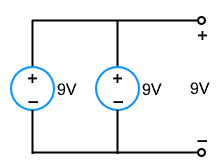
Here two voltage sources of 9V are connected in parallel. The net voltage across terminals will be 9V. It acts as a single voltage source with double current capacity.
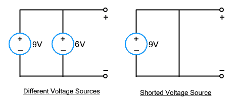
However, two different voltage sources must not be connected directly in parallel. They can be used if there are other electrical components between them. Also, the voltage source must not be shorted as it creates very low resistance between them generating a very large fault current.
In case two same voltage sources are connected in anti-parallel, the net voltage appears to be zero as there will be a huge current flow between the sources. Therefore, it should be avoided.

Related Posts:
- Difference between AC and DC (Current & Voltage)
- Difference Between Current and Voltage
- Difference Between EMF and MMF
- Difference Between Voltage and EMF?
- Difference between Electron Current and Conventional Current
- Difference Between Current Transformer & Potential Transformer
- Difference between Electric Field and Magnetic Field
- Difference Between Electric and Magnetic Circuit
- Differences Between Electrostatic & Electromagnetic Terms
- Difference Between Single Phase and Three Phase Power Supply
- Difference Between Series and Parallel Circuit – Comparison
- Difference Between Overcurrent, Overload and Overvoltage
- Difference Between Electric Current and Electric Charge
- Difference Between Active and Reactive Power – Watts vs VA
- Difference between Analog and Digital Multimeter
- Difference Between a Battery and a Capacitor