PWM Solar Charge Controller – Working, Sizing and Selection
What is Pulse Width Modulation (PWM) Solar Charge Controller?
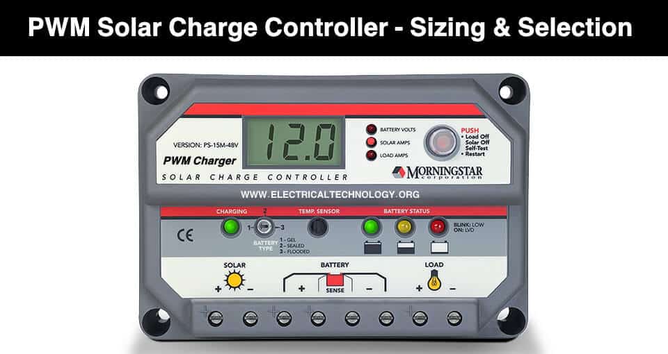
What is Pulse Width Modulation Or A PWM Charge Controller?
A PWM (Pulse Width Modulation) controller is an (electronic) transition between the solar panels and the batteries:
The solar charge controller (frequently referred to as the regulator) is identical to the standard battery charger, i.e., it controls the current flowing from the solar panel to the battery bank to prevent overcharging the batteries. As in a standard battery charger, it can accommodate different types of batteries.
The absorption voltage can select the float voltage, and it can often also set the time and tail current. They are best suitable for lithium-iron-phosphate batteries since when the controller is in full charge, it remains at the fixed float or maintains a voltage of about 13.6V (3.4V per cell) for the rest of the day.
The most popular charging profile is the same simple sequence found on a quality mains adapter, i.e., bulk mode – absorption mode – float mode. Entry to bulk charging mode happens at:
- Sunrise in the morning
- If the battery voltage drops down the specified voltage for longer than a specified period, e.g., 5 seconds (re-entry)
This re-entry into bulk mode works better for lead-acid batteries since the voltage drop and drop are more significant than lithium-based batteries, which retain a higher, more stable voltage for the rest of the discharge period.
In the solar charge controller:
- The switch is ON while the charger mode is in bulk charging mode.
- The switch is ON and off when required (pulse width modulated) to keep the absorption’s battery voltage.
- It is OFF at the end of the absorption when the battery voltage decreases to the float voltage.
- The switch is ON and OFF again as required (pulse width modulated) to keep the battery voltage at the float voltage.
Notice that when the switch is off, the panel voltage will be at the open-circuit voltage (Voc). When the button is on the panel, the voltage will be at the battery voltage + the voltage decreases between the board and the controller.
The best match for a PWM controller:
The best matching panel for a PWM controller is a panel with a voltage just above provided for charging the battery and taking into account the temperature, usually, a board with a Vmp (maximum voltage) of about 18V to charge a 12V battery. They are sometimes referred to as a 12V row even though they have a Vmp of about 18V.
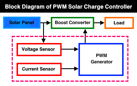
Below is the block diagram of a typical PWM solar charge controller.
Related Posts:
- Basic Components Needed for Solar Panel System Installation
- How to Calculate the Right Size of Solar Charge Controller? PWM & MPPT
PMW 3 Stage Charging
Bulk Charge: The bulk charging level is where the PV device continues much of the battery’s charge. The device will charge the battery with a high current and voltage when the voltage is down. When the voltage at the end of the battery is more significant than this maintenance value while setting, direct charging should stop.
Absorb Charge: Usually, after the first step of charging, the battery will wait for a period to allow the voltage to decrease naturally and then reach the balanced charging stage. The stage is also called constant voltage charging.
Float Charge: It is the last stage of 3-stage charging, known as Trickle charging. The trickle is a slight charging current to the battery at a low rate and steady. Most rechargeable batteries lose power when entirely powered due to self-discharge. If the charging stays at the same low current as the self-discharge rate, it can sustain the charge capacity.
Related Posts:
- How to Design and Install a Solar PV System?
- Calculation & Design of Solar Photovoltaic Modules & Array
PWM Solar Controller Pros:
- The PWM Regulator has matured and established techniques.
- Simple structure and cost-effective
- Easy deployment of the PWM regulator
- The lower budget on a small initiative
PWM Solar Charge Controller Cons:
- Low conversion rate
- Input voltage must balance the bank voltage of the battery.
- Less scalability for device development
- Less Loading Mode
- Less protection;
Related Posts: An introduction to Maximum Power Point Algorithms in PV Systems
The Function of the Solar Charge Controller:
The central charge controller essentially regulates the unit’s voltage and opens the circuit, stopping the charge as the battery voltage rises to a certain amount. More charge controls used a mechanical relay to open or shut off the course, stop or start power from the electrical storage unit.
Generally, 12V batteries are for solar power applications. Solar panels can convey much more voltage than the battery needs to charge. The charge voltage will be maintained at the highest possible level while the time taken to set the electrical storage equipment entirely is minimal. It helps the solar systems to run continuously optimally. The wires ‘ power dissipation is significantly low by running a higher voltage in the solar panels’ cables to the charge controller.
Solar charge controllers can also control the flow of reverse electricity. The charge controllers will discern whether there is no power coming from the solar panels and open the circuit separating the solar panels from the battery devices and stopping the reverse current flow.
Related Posts:
- How Much Watts Solar Panel You Need for Home Appliances?
- A Complete Guide About Solar Panel Installation. Examples & Diagrams
Types of solar Charger controller:
Three types of the solar charge controller
1) Simple 1 or 2 Phase Controls: has switched transistors to regulate the voltage in one or two steps.
2) PWM (pulse width modulated): this is the traditional form of the charge controller, e.g., xantrex, Blue Sky, and so on. It is the industry norm at the moment.
3) Maximum power point tracking (MPPT): MPPT identifies the optimum operating voltage and amperage of the solar panel display and matches that of the electrical cell bank.
Sizing a PWM Solar Charge Controller
PWM controllers are not able to restrict their current performance. They’re just using the current collection. Therefore, if the solar array will generate 40 amps of current and the charge controller you are using is only rated at 30 amps, the controller could be impaired. It is essential to ensure that your charge controller is parallel, compliant with, and correctly sized for your panels.
When looking at a charge controller, many items are looked at in the list of features or tags. A PWM controller would have an amp read with it, e.g., a 30 amp PWM controller. It reflects how many amps the controller can accommodate, in the above example, 30 amps. In general, the amperage and voltage rating are the two things you want to look at in a PWM control.
Next, we want to look at the nominal device voltage. It would inform us what voltage the controller’s battery banks are compliant with. You may use 12V or 24V battery banks in this situation. The controller would not be able to operate on anything higher, such as a 48V battery bank.
Second, the rated current of the battery is important. In this case, let’s assume that you have a 30-amp rating charge controller. A protection ratio of at least 1.25 is recommended, which means that you can average the current from the panels by 1.25 and then equate it to 30 amps. E.g., five 100 watt panels will be 5.29 x 5 = 26.45 amps in parallel. 26.45 Amps x 1.25 = 33 amps, and that will be too much for the controller. The panel will encounter more current than what is valued when exposure to sun rays is above 1000 watts/m^2.
Thirdly, we should look at the maximum input of solar energy. It shows you how many volts you can get to the controller. This controller cannot tolerate more than 50 volts. It is taking a look at making 2 x 100 Watt panels in series with a total of 22.5V (open-circuit voltage) x 2 = 45 volts. In this case, it’s going to be ok to wire these two panels in series.
Fourthly, we should have a look at the terminals. Each controller will typically have the maximum size of the terminal gauge. It is critical when buying wiring for your machine.
Finally, look at the type of battery. It tells us which batteries are compliant with the charge controller. It is essential to verify as you don’t want to get batteries that the controller device cannot power.
Let see the following another basic example for sizing a PWM solar charge controller.
Related Posts:
- Blocking Diode and Bypass Diodes in a Solar Panel Junction Box
- How to Make a Simple Solar Cell? Working of Photovoltaic Cells
Example:
What is the suitable size of PWM solar charge controller for a 100W, 12V solar panel having ISC (Short Circuit current) of 8A?
Solution:
We will have to add the safety factor of 25% current i.e. 1.25 x ISC to find the appropriate size of solar charge controller.
This way; 8A x 1.25 = 10A.
Hence, you can safely use a 10A, 12V of solar charge controller for this basic solar panel system.
Another way, if the total connected DC load is 12V, 95W.
Nominal load current = Total DC load / Nominal System Voltage = 95W / 12V
Nominal load current = 7.91 A
Safety Factor x Nominal load current
1.25 x 7.91 = 9.9A
Finally, a basic power formula method i.e. P = V x I
I = (P/V) x 1.25
I = (95W/12V) x 1.25
I = 9.9A
Note that you will have to apply the same formula for series and parallel connected solar panels and batteries according to voltage and current ratings. You may See more solved example for sizing PWM and MMPT Charge controller in the previous post.
Related Posts:
- Series, Parallel & Series-Parallel Connection of Solar Panels
- How to Wire Solar Panels in Series-Parallel Configuration?
The Discrepancy between PWM and MPPT Solar Load Controllers
The crux of the difference is:
- With the PWM controller, the current is drawn out of the panel at just above the battery level while
- With the MPPT controller, the current draws out of the panel at the “maximum power voltage” button (think of the MPPT controller as a “smart DC to DC converter“).
You also see slogans such as “you’re going to get 20% or more energy harvesting from an MPPT controller.” This extra also differs significantly, and the following is a reference to whether the panel is in full sunlight and the controller is in bulk charge mode. Ignoring voltage decreases, using a simple panel and simple math as an example:
- Panel maximum power current (Imp) = 5.0A
- Panel maximum power voltage (Vmp) = 18V
The charger’s voltage = 13V (battery voltage can vary between, say, 10.8V fully discharged and 14.4V during absorption charge mode). At 13V, the panel amp would be marginally higher than the total power amp, say 5.2A.
With a PWM controller, the output from the panel is 5.2A*13V = 67.6 watts. This sum of power would be drawn regardless of the panel temperature, provided that the panel voltage stays above the battery voltage.
With an MPPT controller, the panel’s power output is 5.0A*18V = 90 watts, i.e., 25 percent higher. However, this is excessively ambitious as the voltage decreases as the temperature increases; thus, assume that the panel temperature rises to 30°C above the normal test conditions (STC) temperature of 25°C. The voltage drops by 4 percent at every ten °C, i.e., a total of 12 percent, the output of the MPPT would be 5A*15.84V = 79.2W, i.e., 17.2 percent more power than the PWM controller.
So, there is an increase in energy harvesting for the MPPT controls, but the percentage increase in harvesting differs considerably over the day.
Related Posts:
- How to Design a Solar Photovoltaic Powered DC Water Pump?
- Parameters of a Solar Cell and Characteristics of a PV Panel
Advantages of PWM Charger
Charging a solar-powered battery is a unique and challenging challenge. In the old days, essential on-off regulators were used to reduce the battery from gas when the solar panel provided excess electricity. However, as the solar systems evolved, it became apparent how much these simplistic instruments had messed with the charging process.
On-off regulators’ experience has been early battery errors, rising load disconnects, and increasing consumer frustration. PWM has recently emerged as the first breakthrough in the charging of solar batteries. PWM solar chargers use hardware similar to most modern, high-quality battery chargers.
As the battery voltage exceeds the control limit, the PWM algorithm slowly decreases the charging current to prevent the battery from being heated and gaseous, while charging begins to return the total amount of energy to the battery in the shortest time possible. It results in better charging efficiency, fast recharging, and a long-lasting battery at maximum power.
Also, this new way of charging solar batteries offers some very fascinating and unusual PWM pulsation advantages.
These include:
- Ability to restore reduced battery power and dissipate the battery
- Dramatically boost the approval of the battery charge.
- Retain high overall battery capacity (90 percent to 95 percent) relative to on-off controlled state-of-charge ranges usually between 55 percent and 60 percent.
- Equalize the drift cells of the battery.
- Limit the heating and gasification of the battery.
- Automatically compensate for the age of the battery.
- Self-regulation of voltage rises and temperature effects in solar systems
Related Posts:
- How to Wire Batteries in Series-Parallel to a Solar Panel?
- How to Wire Batteries in Parallel to a Solar Panel and UPS?
Choosing the Best Solar Controller
The PWM is a decent low-cost option:
- For smaller devices
- Where the reliability of the device is not essential (the charging process)
- For solar panels with a nominal voltage (Vmp) of up to 18V for charging a 12V battery (36V for 24V battery, etc.)
- The MPPT controller is ideally suited for:
- For more extensive networks where an additional 20%* or more energy harvesting is worthwhile;
- Where the solar array voltage is considerably more significant than the battery voltage, e.g., using house panels, for charging 12V batteries;
Related Posts:
- How to Wire Solar Panel to 12V DC Load and Battery?
- How to Wire Solar Panel to 120-230V AC Load and Inverter?
Applications
In recent days, the method of producing electricity from sunlight has become more common than other alternative sources, and photovoltaic panels are free of emissions and do not require high maintenance. Here are few examples where we are using solar energy.
- Street lamps use photovoltaic cells to transform sunlight to DC electrical charge. This machine uses a solar charge device to store DC in the batteries and uses it in several locations.
- Home systems use the PV module for house-holding purposes.
- The hybrid solar panel uses various energy sources to provide full-time backup supplies to other sources.
Note: This Article is published by www.electricaltechnology.org
Related Posts:
- How to Wire Batteries in Series to a Solar Panel and UPS?
- How to Wire Solar Panels & Batteries in Series-Parallel Connection?
- How to Wire Solar Panels in Series & Batteries in Parallel? 12/24/48V System
- How to Wire Solar Panels in Parallel & Batteries in Series? 24V System
- How to Wire Solar Panel & Batteries in Parallel for 12V System
- How to Wire Solar Panel & Batteries in Series for 24V System
- Solar Power Plant – Types, Components, Layout and Operation
- Batteries in Photovoltaic Systems – Applications & Maintenance