How to Calculate the Right Size of Solar Charge Controller?
What is Solar Charge Controller? Types, Sizing and Selection of PWM & MPPT Charge Controllers
Solar charge controllers are a vital part of any solar installation. They secure your battery storage components and ensure that it runs smoothly and reliably over the life of your device. In the following article, we will discuss an Introduction to DC-DC power converters, Charge controllers, and MPPT in a Solar PV system.
What are Solar Charge Controllers?
The charge controller in your solar installation is present between the energy source (solar panels) and the storage room (batteries). Charge controllers keep your batteries from being overcharged by limiting the volume and charge intensity of them. They often avoid the battery from being depleted by shutting down the device if the storage power dropped below 50 percent capacity. The batteries are getting charged at the right voltage level. It helps to protect the life and health of the batteries.
Related Posts:
- Basic Components Needed for Solar Panel System Installation
- An introduction to Maximum Power Point Algorithms in PV Systems
DC-DC Converters:
DC-DC converters are widely used to convert unregulated or uncontrolled DC voltage to a regulated or controlled DC voltage level as shown in figure 1.
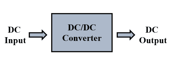
Other than the uncontrolled voltage to controlled voltage these converters convert the voltage from one level to another level (high or low). For example, we have a PV system that produces 24 V dc output voltage but the inverter AC output needs to be 230 V, so we require a higher input dc voltage at the inverter’s input.
So, to obtain that we connect a dc-dc converter in between the PV array and the inverter. These dc-dc converters play a very significant role in our solar PV system. They are used as charge controllers, maximum power point trackers, and acts as an interface along with PV source for different types of loads. Their application also includes power bus regulation, Current boosting, and noise isolation.
In the DC to DC converter both the input and the output side have a DC flow. It is possible to determine input DC power if we know the input voltage and current, similarly, we can determine the output power if we know the output voltage and current. Once we know the input and output power the efficiency of the power converter can be easily determined.
Let us take an example of a DC-DC converter where a battery of 50 V is connected, supplying an input current of 8 A. At the output of the converter the voltage measurement shows a voltage of 100 V and current measurement shows a current of 3.6 A. Determine the input and output power, power loss in the converter, and efficiency of the converter.
- Input voltage = 50 V
- Input current = 8 A
- Output voltage = 100 V
- Output current = 3.6 A
Thus, Input power = Input voltage × Input current
Input power = 50 × 8 = 400 W
Similarly, the output power can be determined as follows;
Output power = Output voltage × Output current
Output power = 100 × 3.6 = 360 W
The power loss in the converter can be determined as follows;
Power loss = Input power – Output power
Power loss = 400 – 360 = 40 W
Efficiency of the converter is determined as follows;
Efficiency % = (output power/input power) × 100
Efficiency % = (360/400) × 100 = 90 %
Related Posts:
- How to Design and Install a Solar PV System?
- Calculation & Design of Solar Photovoltaic Modules & Array
Working & Function of Charge Controllers:
In layman’s terms, you can consider a solar charge controller as a normal regulator which prolongs the life of solar batteries. In most solar charge controllers, the current passes through a semiconductor that serves as a valve to regulate the current.
Charge controllers often keep the batteries from being overcharged by reducing the battery’s flow to exceed a specific voltage. The over-charging of batteries can be especially harmful to the battery itself, so the charging controllers are particularly critical.
It is the controller that helps to control the charge flow from and to the battery. It maintains the long battery life and performance by preventing deep discharge and overcharge of the battery. When a PV module is connected to a battery through a charge controller, the charge controller would disconnect the PV from the battery to avoid overcharging.
Similarly, when a battery is connected to a load through a charge controller, the controller will disconnect the load from the battery if it detects over-discharge. Such an ability of the charge controller helps in prolonging the life and performance of the battery.
Overcharge and deep discharge of the battery are detected by measuring the voltage level of the connected battery. In overcharge, the battery voltage increases above a certain voltage level similarly in case of deep discharge the battery voltage decreases below a certain voltage level.
The charge controller can disconnect the battery in both these above-mentioned conditions. The charge controller also reconnects the battery when the voltage level has reached within the normal operating level.
Due to overcharge the voltage level of the battery reaches high and the charge controller disconnects the battery from the PV module (or charging DC source), but when the level of the voltage falls due to utilization of the battery by the load the charge controller detects this voltage drop and reconnects the PV module (or charging DC source) to charge the battery.
Such a similar thing can also observe in case of deep discharge when the battery gets cut-off (from load) due to a drop in voltage below a certain level. Now if the battery is an undercharging condition, the terminal voltage level will rise after a while due to the charging process. This rise in voltage level is detected and if it is above a low cut-off voltage level the controller will reconnect the battery to the load so that the load can utilize the energy stored in the battery.
Solar charge controllers also provide several other essential features, including overload safety, low voltage disconnect, and reverse current blockage.
Overload protection: Charge controllers have the essential role of protection against overload. If the current flowing into your battery is far higher than the circuit can handle, your device can overload. It can lead to overheating or even explosions. Charge controllers avoid the overload from happening. In larger systems, double safety protection with circuit breakers or fuses is also essential.
Low voltage disconnects: This acts as an automatic disconnection of non-critical loads from the battery when the voltage drops below the defined threshold. When it is powered, it will immediately reconnect to the battery. It is going to avoid over-discharge.
Blocks the flow of Reverse Currents: Solar panels send the current through the battery in single direction. At night, panels can, of course, transfer some of the charges in reverse order. It can trigger a minor discharge of the battery. Load controls avoid this from occurring by serving as a valve.
Related Posts:
- How Much Watts Solar Panel You Need for Home Appliances?
- A Complete Guide About Solar Panel Installation. Examples & Diagrams
Types of Charge Controllers:
The following are the two widely used charge controllers;
- Maximum Power Point Tracking (MPPT) charge controllers
- Pulse Width Modulation (PWM) charge controllers
In the case of MPPT charge controllers, the voltage across the battery bank and the PV array is different. This type of charge controller operates at the maximum power point of the PV array to deliver the maximum possible power available from the irradiance.
The kind of charge controllers makes it possible to have PV array voltage higher than the voltage of the battery bank connected to our system. The advantage is that the higher the voltage lesser will be the current for the same flow of power. Thus, we can use the small gauge wire which reduces the cost of the wire in the system.
On the other hand, the Pulse Width Modulation (PWM) charge controllers have identical voltage across the PV array and the battery bank connected to the system.
Related Posts:
- Blocking Diode and Bypass Diodes in a Solar Panel Junction Box
- How to Make a Simple Solar Cell? Working of Photovoltaic Cells
Various Features of the Charge Controller:
The various voltage and current level of the charge controller can be defined as follows;
- Nominal system voltage: This voltage represents the voltage at which the charge controller and the battery operate in a solar PV system.
- Nominal Load current: This represents the maximum load current that a charge controller should handle.
- Nominal PV array current: This represents the maximum PV array current that the charge controller should be able to handle. It is the short-circuit current of the entire PV array. While designing a safety factor of 1.25 is considered for variation in determined short-circuit current under non-STC (Standard Test Condition).
- Charge regulator set points: The function of the charge controller is to charge and discharge the battery, it senses the terminal voltage (i.e. state of charge or commonly known as SOC) and decides either to disconnect it from the load to avoid the deep discharge or to disconnect it from its PV array source to avoid the overcharge of the battery. Such a controller has set points upon which it takes decisions either to connect or disconnect the load or charging source (i.e. PV array).

- Voltage regulation setpoint (VR): This represents the maximum voltage up to which a battery can be charged without getting overcharged. If this setpoint is reached then the controller will disconnect the battery bank from the PV source or it may regulate the current supplies to the batteries.
- Voltage regulation hysteresis (VRH): This represents the difference between the VR and the voltage at which the charge controller will reconnect the battery to the PV source for charging. If this difference is very small then the control will be oscillatory (connect and reconnect frequently) which will eventually result in deterioration in the performance and life of the battery. But having a difference might also lead to some overcharging in each cycle. So, a balance has to be made while stating the VRH. The VRH also helps us understand how effective is the charge controller at charging the battery.
- Low voltage disconnect (LVD): This represents the minimum voltage that up to which discharge of a battery is allowed without getting into the deep discharge. This is also known as the depth of discharge (DOD) of a battery. It is strongly recommended to avoid discharge below this level to avoid the deterioration of the life and performance of the battery. The charge controller can disconnect the battery from the load if it detects the LVD and avoids the deep discharge of the battery.
- Low voltage disconnect hysteresis (LVDH): This represents the difference between the LVD and the voltage at which the battery can be reconnected to the load. It is not kept too small, as this may result in frequent connection and disconnect. Which can further reduce the life of the battery.
Related Posts:
- Series, Parallel & Series-Parallel Connection of Solar Panels
- How to Wire Solar Panels in Series-Parallel Configuration?
How to Select a Proper Rated Solar Charge Controller?
The following two examples shows how to select a right size solar charge controller for solar panel and array system having the appropriate nominal current rating in amperes at given rated nominal voltage and load in watts.
Example 1:
Let us now take an example to understand the above parameters, a living room has the following DC loads which are rated at 24 V;
- Three 20 W lamps
- One 25 W fan
All the above-mentioned loads are powered by two parallel connected PV modules, each PV module has a maximum power point current IMP of 5 A and short-circuit current ISC of 7 A. What will be the nominal system voltage, nominal PV array current, and Nominal load current of the charge controller?
Total DC load = (No. of lamps × Wattage of each lamp) + (No. of fans × Wattage of each fan)
Total DC load = (3 × 20) + (1 × 25) = 60 + 25 = 85 W
The nominal system voltage of the charge controller is the same as the rated voltage of the load and the PV array (Nominal system voltage of the charge controller = 24 V)
Nominal PV array current = 2 × 7 (short-circuit current of each PV module is 7 A and are connected in parallel)
Nominal PV array current = 14 A
A safety factor of 1.25 is considered for variation in determined short-circuit current under non-STC (Standard Test Condition).
Considering the safety factor of 1.25 the Nominal PV array current is 1.25 × 14 = 17.5 A
Nominal load current = Total DC load / Nominal system voltage = 85 / 24
Nominal load current = 3.5416 A
Thus, the charge controller should be able to handle a current of about 3.5416 A at the output side.
Example 2:
Let us take another example to practice it; an auditorium has the following DC loads which are rated at 12 V;
- Three 30 W lamps
- One 20 W fan
All the above-mentioned loads are powered by two parallel connect PV modules, each PV module has a maximum power point current IMP of 3 A and short-circuit current ISC of 5 A. What will be the nominal system voltage, nominal PV array current, and Nominal load current of the charge controller?
Total DC load = (No. of lamps × Wattage of each lamp) + (No. of fans × Wattage of each fan)
Total DC load = (3 × 30) + (1 × 20) = 90 + 20 = 110 W
The nominal system voltage of the charge controller is the same as the rated voltage of the load and the PV array (Nominal system voltage of the charge controller = 12 V)
Nominal PV array current = 2 × 5 (short-circuit current of each PV module is 5 A and are connected in parallel)
Nominal PV array current = 10 A
A safety factor of 1.25 is considered for variation in determined short-circuit current under non-STC (Standard Test Condition).
Considering the safety factor of 1.25 the Nominal PV array current is 1.25 × 10A = 12.5 A
Nominal load current = Total DC load / Nominal system voltage = 110W / 12V
Nominal load current = 9.1666 A
Thus, the charge controller should be able to handle a current of about 9.1666 A at the output side.
Related Posts:
- How to Design a Solar Photovoltaic Powered DC Water Pump?
- Parameters of a Solar Cell and Characteristics of a PV Panel
Maximum Power Point Tracking (MPPT):
The load connected to a PV module determines the power delivered by the module, take a look at the I-V and the P-V curve shown in figure 3 below.
It can be observed from the above figure that at the short circuit condition i.e. at V = 0, maximum current is delivered by the module known as short circuit current ISC. But if we gradually increase the voltage across the load by varying the load the power delivered to the load also increases.
So, the increase in the voltage causes the power to increase up to a certain point, the point beyond which the increase in voltage further causes a decrease in the power is called as Maximum Power Point (MPP). So, the I-V curve of a PV module has a point that corresponds to the maximum power known as Maximum PowerPoint or in short MPP.
It is required that the load connected to the PV module should be operated at a voltage and current which corresponds to this maximum power point to obtain the maximum power from the PV modules. The operating point is the point of intersection of I-V characteristics of PV modules to a load.
Manufacturers rated their PV modules for peak power output. But the output power of PV modules not only depends on the available solar irradiance but also on the combination of voltage and current. For example during mid-day when the sun is high the module will not deliver the power if it is in the open circuit or short circuit condition.
So, there is an operating point on the I-V curve where the product of voltage and current will deliver the maximum power. But this maximum operating point changes with the change in the intensity of the radiation falling on the solar PV modules. Thus, to obtain that maximum power there are electronic devices that will ensure that the PV modules will operate at maximum power at all the level of irradiance throughout the day. This idea of operating the PV module at its maximum power is called Maximum Power Point Tracking (MPPT).
Practically there are changes in the I-V curve of the PV module due to the change in the intensity of the radiation falling on the module. Thus, it is not possible to keep the PV operated at the MPP for a chosen load. The solar radiation is less at around 9 a.m. and it gradually increases till noon. This increase in the intensity of the radiation will cause the I-V curve of the module to change as shown in figure 4 below.

This results in the change of the operating point for a given load. The operating points for 1 p.m., 11 a.m., and 9 a.m. are denoted by A, B, and C respectively. But the maximum operating points for 1 p.m., 11 a.m., and 9 a.m. are denoted by A’, B’, and C’ respectively.
Thus, if we need to obtain maximum power from the PV module the operating points A, B, and C should be brought closer to A’, B’, and C’ respectively and this is done by an MPPT device. The MPPT device does the job of getting the operating point closer to the maximum power point at a different level of solar radiation.
It helps in extracting the maximum power available from the PV module under any irradiance and temperature. It makes the use of an MPPT algorithm and an electronic circuit to get the job done. The idea is based on the principle of matching the impedance between the PV module and the connected load which is essential to transfer the maximum power.
Thus, when the impedance of the PV source and the load matches maximum power is transferred from the PV source to the load. If the ratio of module voltage at maximum power to module current at maximum power matches the impedance of the connected load, maximum power transfer takes place.
But practically it is not possible to have a matching of this ratio to the impedance of the load, hence the MPPT device does that operation of impedance matching to deliver the maximum power at available irradiance and temperature. Manufacturers combine the functions of the charge controller and MPPT into one device which is widely known as the MPPT charge controller. Both MPPT and the charge controller are two different and independent functions but are widely used as one device to serve two purposes.
Related posts:
- How to Wire Batteries in Series-Parallel to a Solar Panel?
- How to Wire Batteries in Parallel to a Solar Panel and UPS?
Sun-tracking and MPPT for Maximizing the Power Output:
The sun-tracking is not the same as the MPPT tracking, it is a mechanical tracking of a solar PV module in such a way that the sun ray’s incident on the modules is always perpendicular. The module should mechanically face the sun to obtain maximum power during that time of the day.
If the modules are not perpendicular to the sun rays falling on it most of the sunlight would be reflected from the modules. The solar module produces maximum output power for given sunlight when the angle of the light and the module are perpendicular to each other (i.e. 90o) as shown in figure 5.
When the angle of the incident of light is less than or greater than 90o as shown in figure 5 then it will produce output power lower than the maximum output power capability of the module. When the light falls on an angle greater or lesser than 90o some part of the light is reflected, and the light utilized by the module is less than the actual falling on it.
This results in a reduction of the output power generated by the module. It is due to this reason that we must have mechanical sun-tracking to generate maximum possible electricity.
Specifications of the MPPT Charge Controller:
PV Input
Maximum input power: This represents the maximum power that the MPPT charge controller can handle from the connected PV array.
Maximum open circuit voltage: This represents the maximum open-circuit voltage that the MPPT charge controller can handle.
MPPT tracking voltage range: This represents the voltage level range that the MPPT charge controller can handle.
DC Output to the Battery
Nominal battery voltage: This represents the voltage at which the battery operates in a connected system.
Voltage regulation setpoint (VR): It is the maximum level of voltage up to which we can charge a battery without causing the overcharge. Once this level has reached the charge controller will either disconnect the battery from the PV source or will regulate the current delivered to the connected battery.
Low voltage disconnect (LVD): It represents the minimum voltage up to which the discharge of the battery is allowed without causing the deep discharge. Also known as Depth of discharge (DOD). When the battery level reaches the DOD level the MPPT charge controller disconnects to avoid overcharging.
Maximum charging current: It represents the maximum current that an MPPT charge controller can handle from the PV array. It is a PV array short circuit current. While designing a safety factor of 1.25 is used due to variation at non-STC operations.
DC Load Control
Nominal voltage: This represents the charge controller’s maximum load voltage which it should be able to handle.
Maximum current: This represents the charge controller’s maximum load current which it should be able to handle.
Related Posts:
- How to Wire Solar Panel to 12V DC Load and Battery?
- How to Wire Solar Panel to 120-230V AC Load and Inverter?
How to Select the Right Size MPPT Charge Controller?
Let us take some examples to understand the above-mentioned specifications numerically.
Example 3:
Consider a 500-watt PV array that operates at 24 V DC and has a battery bank of 12 V DC. Determine an MPPT charge controller rating s for this given system.
- Solar PV array wattage = 500 W
- Solar PV array operating voltage = 24 V
- Battery pack operating voltage = 12 V
The input power to the MPPT controller is 500 W, the solar PV array is connected at the input side of the MPPT charge controller and the battery is connected at the output side of the MPPT charge controller. Thus, the battery acts as a load to the system. The data specifies the output voltage. Assuming 100 % efficiency we can determine the output current for its load.
Power = Voltage × Current
Current = Power / Voltage = 500W / 12V = 41.66 A
Thus, we would require a 12 V, 41.66 A MPPT for the above system, we can increase the current value by 25 % considering some conditions that occur causing the panel to produce more power. Thus, we can take it as 52 A. So, 12 V, 52 A MPPT charge controller would be suitable for the above system. Note that the MPPT charge controller should be able to handle the open-circuit voltage and the voltage at the maximum power point of the connected PV array.
Let us take another example where we have to design a 140 WP Solar home system with a PV module of 70 W having an open-circuit voltage of 20 V and voltage at maximum power point of 16 V. The voltage of the battery bank is at 12 V. Determine a suitable MPPT charge controller rating for this home solar design.
Let us connect the available PV module in series.
Thus, the open-circuit voltage of the system would become = 2 × 20 = 40 V
Voltage at maximum power point would be = 2 × 16V = 32 V
Peak power of the system would be = 2 × 70W = 140 W
The input power to the MPPT charge controller is 140 W if we assume 100 % efficiency. And the available battery voltage at 12 V, then the current to the battery pack can be determined as follows;
Power = Voltage × Current
Current = Power / Voltage = 140W / 12V = 11.66 A
Thus, we would require a 12 V, 11.66 A MPPT for the above system, we can increase the current value by 25 % considering some conditions that occur causing the panel to produce more power. Thus, we can take it as 15 A. So, 12 V, 15 A MPPT charge controller would be suitable for the above system.
Again, it is important to note that the MPPT charge controller should be able to handle the open-circuit voltage and the voltage at the maximum power point of the connected PV array.
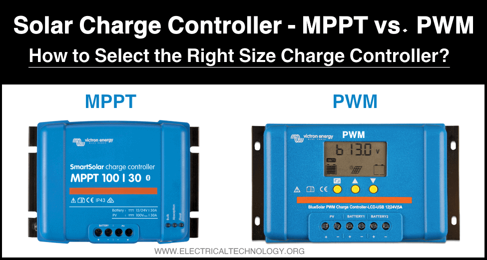
Which Solar Charge Should I Select? PWM or MPPT?
When it comes to deciding the controller size, you need to know whether you are using a PWM or an MPPT controller. Do you know that an incorrect selection of solar charge controllers can result in a loss of up to 50% of the solar system’s energy?
| Solar Panel | Battery | Solar Charger |
| 12V | 12V | PWM or MPPT |
| 24V | 24V | PWM or MPPT |
| 24V | 12V | MPPT (Recommended) |
Solar charge controllers are measured based on your solar array current and your solar system’s voltage. Usually, you want to make sure that you have a charge controller that is big enough to accommodate the amount of power and current produced by your panels.
Usually, charge controllers are present in 12, 24, and 48 volts. Amperage ratings can vary from one to 60 amps and voltage ratings from six to 60 volts. If you have not yet weighed your setup or estimated your energy requirements, we suggest using the solar panel calculator. It will allow you to scale your solar panels and all the other components of your device.
If your solar system was 12 volts and your amps were 14, you will need a solar charge controller with at least 14 amps. However, you need to add 25% to the minimum amps that your solar charger controller would have at 17.5 amps due to environmental considerations. But you will require a solar charger controller with a rating of 12 volts and 20 in this situation.
Here are few more details depending on the type of charge controller you have mounted on your device.
| Battery Condition @ 25 °C (77 °F) | Nominal Battery Voltage | ||
| 12V | 24V | 48V | |
| Battery during equalization charge | Over 15 | Over 30 | Over 60 |
| Battery near full charge while charging | 14.4 to 15.0 | 28.8 to 30.0 | 57.6 to 60.0 |
| Battery near full discharge while charging | 12.3 to 13.2 | 24.6 to 26.4 | 49.2 to 52.8 |
| Battery fully charge with light load | 12.4 to 12.7 | 24.8 to 25.4 | 49.6 to 50.8 |
| Battery fully charged with heavy load | 11.5 to 12.5 | 23.0 to 25.0 | 46.0 to 50 |
| No charge of discharge for 6 hours – 100% charged | 12.7 | 25.4 | 50.8 |
| No charge of discharge for 6 hours – 80% charged | 12.5 | 25 | 50 |
| No charge of discharge for 6 hours – 60% charged | 12.2 | 24.4 | 48.8 |
| No charge of discharge for 6 hours – 40% charged | 11.9 | 23.8 | 47.6 |
| No charge of discharge for 6 hours – 20% charged | 11.6 | 23.2 | 46.4 |
| No charge or discharge for 6 hours – fully discharged | 11.4 | 22.8 | 45.6 |
| Battery near full discharge while discharging | 10.2 to 11.2 | 20.4 to 22.4 | 40.8 to 448 |
Related Posts:
- MPPT Solar Charge Controller – Working, Sizing and Selection
- PWM Solar Charge Controller – Working, Sizing and Selection
FAQ
Do you need a controller for solar charges?
Typically, yes. No charge controller necessary for small 1 to 5-watt screens. If the panel sets 2 watts or less for every 50 hours of battery life, you usually don’t need a charge controller. It’s far above that.
What’s going to influence my decision-making when I pick a charge controller?
The following considerations should check out when purchasing a charge controller:
- The budget;
- The life of technology
- The temperature where the machine gets installed: specific charge controllers perform well in cooler climates.
- How much electricity is needed, and how many solar panels are available!
- The size, number, and type of batteries that you use on your device
Can you use more than one charge controller?
In cases where a single charge controller is not capable enough to handle the output of your solar panel array, you can use multiple charge controllers with one battery bank. Using an MPPT (Maximum Power Point Tracker) charge controller can be the safest way to connect the device as arrays have different maximum power points.
However, it is recommended to use the same form of the charge controller if you use more than one. Meaning, if you are using a single MPPT charge controller, all your solar charge controllers should be of MPPT type. Make sure that all of your controllers have the same battery setting input as well.
What is the upper voltage limit?
Both charge controllers have a maximum voltage limit. It applies to the highest voltage that controllers can manage safely. Make sure you know what the upper voltage limit of your controller is. Otherwise, you could end up burning off your solar charge controller or causing other safety hazards.
Common charge controller errors and mistakes
Due to all the various components of a solar installation, it can be possible to make an error in the installation process. Here are some widely made mistakes when it comes to solar charge controllers.
- Do not attach AC loads to the load controller. Only DC loads can connect to the output of the charge controller.
- You should mount the charge controller next to the battery as the battery voltage’s accurate calculation is an essential aspect of the solar charge controller’s functions.
Conclusion
If you are in an RV ( off-grid cabin), solar charge controllers are an integral part of your solar installation. Researching and weighing your choices before you make that investment helps mean choosing the right controller for you and your device and avoiding the hassle.
Related Posts:
- How to Wire Batteries in Series to a Solar Panel and UPS?
- How to Wire Solar Panels & Batteries in Series-Parallel Connection?
- How to Wire Solar Panels in Series & Batteries in Parallel? 12/24/48V System
- How to Wire Solar Panels in Parallel & Batteries in Series? 24V System
- How to Wire Solar Panel & Batteries in Parallel for 12V System
- How to Wire Solar Panel & Batteries in Series for 24V System
- Solar Power Plant – Types, Components, Layout and Operation
- Batteries in Photovoltaic Systems – Applications & Maintenance