Batteries in Photovoltaic Systems – Applications & Maintenance
Batteries: Fundamentals, Applications and Maintenance in Solar PV (Photovoltaic) Systems
In a standalone photovoltaic system battery as an electrical energy storage medium plays a very significant and crucial part. It is because in the absence of sunlight the solar PV system won’t be able to store and deliver energy to the load.
During non-sunshine hours we need this stored energy in a standalone system to run our appliances, whereas in a grid-tied system if the grid is operational then the required amount of energy can be provided by the grid in case of low or even non-sunshine hours.
With the advance in technology and the increase in the market, the cost of solar PV modules is decreasing whereas the cost of batteries is becoming a significant part of a standalone system. Non-optimal use of batteries can result in the reduced life of such a significant device in the system.
Thus, here in this article, we are going to see some important practical and technical details of batteries as well as their utilization and maintenance in the solar photovoltaic system.

Battery Fundamentals
Our portable electronic devices like smartphones, smartwatches, laptops, torches, and power banks, etc all these things require some portable supply of energy to use these devices. The conventional AC supply available cannot be used to run such devices hence we need a portable DC supply. So, to provide such a portable DC supply a device having electrical energy stored known as the battery is used.
The charge stored in the battery is utilized to supply the required power to those portable electronic and electrical devices whenever it is necessary. Electrical energy is stored in a form of chemical energy and when required this chemical energy is converted into electrical energy to fulfill the application’s energy demand.
The utilization of the battery is similar to that of the water storage tank, turn the tap on when water is required and turn it off when water is not required, and restore the water when the tank is empty. In battery instead of water the charge is stored and depending on the energy required the charge storage capacity (size of the battery) is determined.
A battery is a two-terminal device, one is the positive terminal and the other is the negative terminal. There is a voltage difference in these two terminals when the battery is charged. It is due to this difference in the terminals that drive the current when it is connected to an electrical or electronic appliance.
In the market, there are different types of batteries available which come in various shapes, sizes, voltage ratings, storage capacities, charge-discharging cycles, shell life, and technologies. There are rechargeable and non-rechargeable batteries.
The batteries used in smartphones, smartwatches, laptops, and torches, etc are of low capacity whereas batteries used in electric vehicles, motors, PV systems, and other renewable energy systems are of high capacity. So, depending on the application a particular type of battery is chosen.
- Related Post: Why Battery Rated in Ah (Ampere hour), Not in VA.
Rechargeable Batteries
Just like refilling a storage water tank, a battery is also required to restore the charge in a standalone solar PV system. The charge level of the battery drops as it is utilized for fulfilling the load demand just as in the case of a storage water tank where the water level drops when it is utilized.
As soon as the charge level just like that of water level drops it is required to restore the charge continuously to avoid any disruption in the operation of the system. This process of restoring the charge or refilling the electrical energy in the batteries is known as “Charging”.
In this process of charging the electrical energy is supplied to the batteries where it is converted into chemical energy. The process of consuming the electrical energy from the batteries is known as “Discharging”. In the process of discharging the chemical energy from the batteries is converted into electrical energy which is supplied to the load.
Thus, the battery has a charging and discharging process. One charging and discharging process of a battery are known as one charge cycle of the battery. Some batteries have multiple charge-discharge cycles while some don’t, the batteries with multiple cycles are known as “Rechargeable Batteries”.
Such rechargeable batteries with many cycles are widely applicable in solar PV applications as they ensure the continuity of the power to the load in the presence of low or even no sunlight, without which the implementation of a standalone solar PV system would be very unreliable and difficult.
- Related Post: Difference Between a Battery and a Capacitor
Working of a Battery
A battery is a combination of two or more units of voltaic cells (electrochemical cells) that are connected in series or parallel. It deals with electrical and chemical energy hence the name electrochemical cell, it is also termed as simply a “cell”.
Now, this single unit of a voltaic cell or electrochemical cell consists of two half cells as shown in figure 1 below. Each half-cell has an electrode and an electrolyte. This two half-cell which makes a single unit of electrochemical cells are connected electrically to each other by a salt bridge and the electrodes of different metals are used in the two half-cells as shown in figure 1.
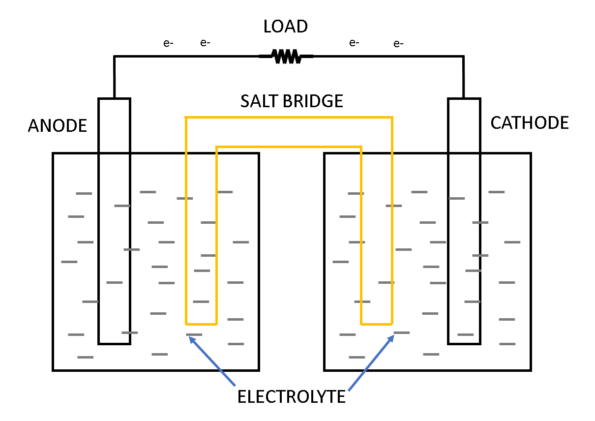
A chemical reaction occurs at the metal electrode in each half-cell. Two chemical reactions occur during the cell’s operation; one is an oxidation reaction and the second is a reduction reaction. The process in which the electrons are lost or released is known as oxidation and the process in which the electrons are accepted or gained is known as reduction.
This process of oxidation and reduction happens at the time of charging and discharging of the electrochemical cell. During charging, the oxidation takes place at the cathode terminal (negative terminal) and reduction takes place at the anode terminal (anode terminal) as shown in figure 2.
A charging and discharging process together is called a single cycle. A fully charged battery is when it is filled with charge and it is said to be completely discharged when its charge is completely utilized.

Components of the Battery Cell
As we saw various components of the battery cell such as anode, cathode, salt bridge, etc we will see the functions of these components below:
Anode: It is referred to as positive lead or positive terminal or positive node. This positive electrode gives up the electrons to the external circuit which results in oxidation during the discharging process.
Cathode: It is referred to as negative lead or negative terminal or negative node. This negative electrode gains electrons from the external circuit which results in the reduction of the electrons during the discharging process.
Electrolyte: The electrolyte acts as a conducting medium for the ions between the anode and the cathode. An electrolyte is also referred to as a medium through which the current flows internally in a battery. It is water with other dissolved solvents along with acids, alkalis, and salts.
Salt bridge: Sometimes referred to as a separator. It is a porous material that isolated the two electrodes but yet keeps them connected from each other otherwise the chemical reaction would stop.
Related Post: Basic Components Needed for Solar Panel System Installation
Types of Batteries
There are a variety of batteries available in the market and each of them is suitable for a particular application. They are broadly classified as rechargeable and non-rechargeable batteries.
Non-rechargeable Batteries: This type of battery is one time usable i.e. the electrochemical reaction is non-rechargeable batteries is not reversible. Hence, such a battery cannot be charged again. They are popular because easy to use, simple, portable, requires no or even less maintenance, and are available in different sizes and shapes.
The sizes are referred to as A, AA, AAA, C, D, etc, and shapes such are cylindrical, coin, cuboid, etc such are mainly applicable in wristwatches, toys, etc. These batteries are available in a capacity below 20 Ah and can operate in a temperature range of – 40 OC to 70 OC. They have high shell life and are cheaper. One of the most commonly known non-rechargeable batteries is the pencil cell i.e. the zinc chloride battery.
There are other such batteries used for different applications such as Aluminum cells, magnesium cells, mercuric oxide cells, etc. The battery which is utilized for the solar PV application requires frequent charge and discharge operation to supply the load demand. Thus, the non-rechargeable batteries are not suitable for Solar PV operation.
Rechargeable Batteries: The batteries which are capable of converting chemical energy into electrical energy and can do the vice-versa process i.e. convert the chemical energy into electrical energy are called are rechargeable batteries.
These batteries are the most widely used in the world for various applications such as automotive power supply, lighting, camera, electric vehicles, smartphones, laptops, and solar PV systems, etc. They are easily manufactured and can store charge in a wide range of capabilities.
Some of the commonly used batteries are Nickel-metal oxide, lead-acid, nickel-cadmium, lithium-ion polymer, etc. The charge storage capacity of the battery is reflected by its physical size. Small size batteries have small storage of charge while large size batteries have high storage of charge.
One of the most commonly used batteries in the solar PV system is the lead-acid battery. They are big as they can store high charge and this is the reason, they are most commonly used in the solar PV system.
- Related Post: Types of Batteries and Cells and Their Applications
Battery Parameters
Different parameters of the battery define the characteristics of the battery, which include terminal voltage, charge storage capacity, rate of charge-discharge, battery cost, charge-discharge cycles, etc. so the choice to select batteries for a particular solar PV system application is determined by its various characteristics.
All the above-mentioned parameters affect the performance of the battery and it is important to know and understand these parameters to install, utilize, and maintain a battery pack in a solar PV system. These battery parameters are displayed by the manufacturers and based on this we can select a battery or a set of batteries for our solar PV application. The following are the parameters mentioned by the manufacturers;
Battery Terminal Voltage
The electrical energy is supplied to the load when it is connected across its terminal and current starts flowing through it. The energy flow to the load can only be possible if there is a voltage difference across the battery terminal.
This voltage difference between the two electrodes of the battery terminal is called the battery terminal voltage. This difference in terminal voltage acts as the driving force for the current. The battery terminal voltage is one of the most important parameters that determine the selection of the battery.
Appropriate battery terminal voltage must be chosen for the application or it might not work, sometimes it requires 3 V, sometimes 6 V, or sometimes even 12 V or higher. Usually, batteries with 6 V and 12 V are available for the solar PV system application.
Now each battery is made up of cells and depending on the material its terminal voltage of the cell is determined. To obtain the required 6 V or 12 V the terminal voltage of the cell is not large enough, many such cells are connected in series to add up and obtain the required voltage level. Six cells are connected to form a 12 V lead-acid battery.
The battery terminal voltage changes with several conditions of the battery, one being during the charging and the discharging. When the battery gets charged its terminal voltage increase and decreases when it is discharged.
Related Posts:
- How to Wire Solar Panels in Series & Batteries in Parallel? 12/24/48V System
- How to Wire Solar Panels in Parallel & Batteries in Series? 24V System
Open Circuit Voltage and Terminal Voltage
When the battery is fully charged and no current is flowing then the terminal voltage of the battery is at its maximum and is equivalent to the open-circuit voltage. That is why it is referred to as battery open-circuit voltage VO or electromotive force Vemf.
The terminal voltage of the battery and the open circuit of the battery is not the same. The terminal voltage of the battery is lower than the open-circuit voltage of the battery when its terminals are connected across the load and current starts flowing through it.
This happens because of the internal resistance of the battery. It is due to this resistance that the voltage drop occurs inside the battery. The voltage drop that occurs due to this internal resistance can be calculated by multiplying the current flowing through the battery by its internal resistance i.e. I × Ri.
Therefore, when the battery is connected to the load and current starts flowing then the actual terminal voltage of the battery will be the difference between the open-circuit voltage and the voltage drop due to internal resistance i.e. I × Ri. This can be written in the following way;
VBatt = VO – (I × Ri) ….. (1)
Where,
- VBatt = Battery terminal voltage in Volts.
- I = current flowing through the battery in Amperes when it is connected to the load.
- VO = Open-circuit voltage of the battery in Volts.
- Ri = Internal resistance of the battery in Ohms.
Let us take an example where a battery is having an internal resistance of 0.8 ohms and an open-circuit voltage of 15 V what is the voltage developed across its terminal when it delivers a current of 5 A, 12 A, and 18 A?
| Open-circuit voltage (VO) | Internal resistance (Ri) | Current (A) | VBatt = VO – (I × Ri) |
| 15 | 0.8 | 5 | 11 |
| 15 | 0.8 | 12 | 5.4 |
| 15 | 0.8 | 18 | 0.6 |
From the above table, it can be seen that the voltage appearing across the battery VBatt decreases with the increase in the current so to have a maximum voltage VBatt the internal resistance of the battery should be as minimum as possible.
Related Posts:
- How to Wire Solar Panel & Batteries in Parallel for 12V System
- How to Wire Solar Panel & Batteries in Series for 24V System
Terminologies for Battery Terminal Voltage
Now let us see briefly the various voltage terminologies associated with the battery;
Open-circuit Voltage (VO): This is the voltage that appears across the battery when it is fully charged and no load is connected for the current to flow. It is the maximum possible voltage across the battery terminal.
Nominal Terminal Voltage: The nominal voltage also sometimes referred to as operation voltage is the voltage that appears across the terminals of the battery at which the load can operate. The standard battery operating/ nominal voltages are 3 V, 6 V, 12 V, and so on.
Cut-off Voltage: It is referred to as the voltage up to which the load can operate and below it, the battery should be disconnected from the load to avoid over-discharge of the battery.
Related Post: How to Design and Install a Solar PV System?
Charge Stored Capacity (Coulomb or Ampere-hour “Ah”)
The capacity to store the charge in the battery is called the charge stored capacity, it is measured in Coulomb or ampere-hour. It represents the amount of current (in amperes) it can deliver for a given time (an hour). When we say that the battery charge stored capacity is 1 Ah, it means charge delivered when a constant current of 1-ampere supplies the load for one hour. Mathematically it can be expressed as follows;
Capacity (C) = Current (A) × Hour (h) ….. (2)
Temperature plays a very crucial role in determining the capacity of a battery. It will have different capacities at different temperatures. The capacity provided by the manufacturer is at standard test condition i.e. at 25 oC. hence, one must consider the temperature of the location where the batteries are to be installed to obtain the correct value of capacity according to the location and application.
Now the question lies in how much current a battery can supply? Battery being an energy storage device can supply only a specified fixed amount of current. The amount of current that can be drawn from the battery can be easily determined if we know the duration of discharge time and the charge capacity which is available from the manufacturer. This can be understood from the following equation;
Current (A) = Capacity (Ah) / Discharge Duration (Hours) ….. (3)
It can be very well understood from the above equation that the longer the discharge duration smaller will be the current drawn from the battery and the shorter the discharge duration higher will be the current drawn from the battery.
This can be understood with an example of a storage water tank, if we draw water slowly, we can draw water for a longer period but if we draw water very fast the storage tank will be drained out very soon. So, if our discharge duration happened to be very small then the current drawn will be very high.
This should be avoided as the high current will cause a voltage drop inside the battery due to its internal resistance which will result in reduced voltage available at the battery terminal. Normally in a solar PV system, the discharge duration is high around 15 to 20 hours and so the current drawn will be small. Now let us understand this with an example;
In one case a 200 Ah battery is discharged in 40 hours while in other cases it is discharged in 10 hours. Let’s determine the current drawn in both cases.
- Discharge time 40 hours:
Current (A) = Capacity (Ah) / Discharge Duration (Hours)
Current (A) = 200 / 40 = 5 A
- Discharge time 10 hours:
Current (A) = Capacity (Ah) / Discharge Duration (Hours)
Current (A) = 200 / 10 = 20 A
Now from this example, it is very clear that during longer discharge time i.e. 40 hours the current drawn is low i.e. 5 A, and during shorter discharge time i.e. 10 hours the current drawn is high i.e. 20 A.
It is now easy to determine the electrical energy stored in the battery once the battery terminal voltage and its charge stored capacity are known. This electrical energy is a product of stored capacity and terminal voltage. It can be given mathematically as;
Energy (Watt-hour) = Capacity (Ah) × Voltage (V) ….. (4)
Thus, with large capacity and higher terminal voltage more electrical energy is stored in the battery. Now what will be the power of the battery, generally power in DC is defined as the product of voltage and current. For batteries, the product of terminal voltage and the current drawn from the battery is the power of the battery. Mathematically it can be written as;
Power (Watt) = Current drawn (A) × Terminal Voltage (V) ….. (5)
Let us now take an example to understand the idea of energy and power in the battery. If we have a 12 V battery with a charge capacity of 400 Ah. What will be its power and the stored energy?
Now let us first assume the discharge duration of the battery say 20 hours, now by using the equation below we can determine the current drawn from the battery.
Current (A) = Capacity (Ah) / Discharge Duration (Hours)
Current (A) = 400 / 20 = 20 A
Now that we know the current drawn for 20 hours, we can now easily determine the power of the battery as follows;
Power (Watt) = Current drawn (A) × Terminal Voltage (V)
Power (Watt) = 20 A × 12 V = 240 W
Also, the energy stored in the battery can be easily calculated as follows;
Energy (Watt-hour) = Capacity (Ah) × Voltage (V)
Energy (Watt-hour) = 400 Ah × 12 V = 2400 Wh or 2.4 KWh
Related Posts:
- How to Wire Solar Panel to 12V DC Load and Battery?
- How to Wire Solar Panel to 120-230V AC Load and Inverter?
State of Charge (SOC) and Depth of Discharge (DOD)
Practically the total charge stored in the battery cannot be utilized for the load application. Only a certain percentage of stored charge can be used to run the load, this is referred to as the Depth of Discharge (DOD) limit and is measured in percentage %.
If the battery has a DOD limit of 30 % then only 30 % of the stored charge can be utilized for running the load. If the DOD limit is 60 % only 60 % can be utilized if 70 % only 70 % can be utilized if 80 % only 80 % can be utilized for running the load.
Ideally, the DOD limit of the battery should be 100 % and practically it should be as high as possible. A high percentage of DOD limit is preferred for the solar PV application. The percentage of DOD limit varies for different batteries, for li-ion, it is around 85 to 90 % and for lead-acid batteries which are most popular for solar PV applications, it is about 50 %.
Other than the DOD limit the DOD simply can be defined as the level to which a stored charge is used to its total charge capacity of the battery. The terminal voltage of the battery reduces due to the use of its stored charge i.e. increase in DOD. The terminal voltage of a fully charged battery is higher than the fully discharged or partially discharged battery.
The manufacturers specify the maximum allowable DOD limit for their battery and it is recommended not to discharge the battery below the specified DOD limit as it would reduce the battery life quickly.
State of Charge (SOC): To determine the time of charge it is important to know the present charge level of the battery. This state of present charge level is indicated by the State of Charge (SOC) and is represented in percentage.
For example, a 70 % SOC indicates that 70 % of the total stored charge is present in the battery. The DOD can also be used to present the SOC, DOD is an invert of the SOC. If 70 % of SOC is subtracted from 100 % then we get 30 %, this 30 % represents the DOD of the battery. It can be mathematically expressed by using any of the following equation;
DOD in % = 100 % – SOC in % ….. (6)
DOD in % + SOC in % = 100 % ….. (7)
Let us understand with simple example, If the DOD is 80 % then by using any of the above, we can determine SOC in % as;
DOD in % + SOC in % = 100 %
80 % + SOC in % = 100 %
SOC in % = 20 %
As we continue to use the battery the SOC level decreases and the DOD level increases. It is important to keep in note that the battery should not be drained down below the DOD level specified by the manufacturer to avoid a reduction in the life cycle.
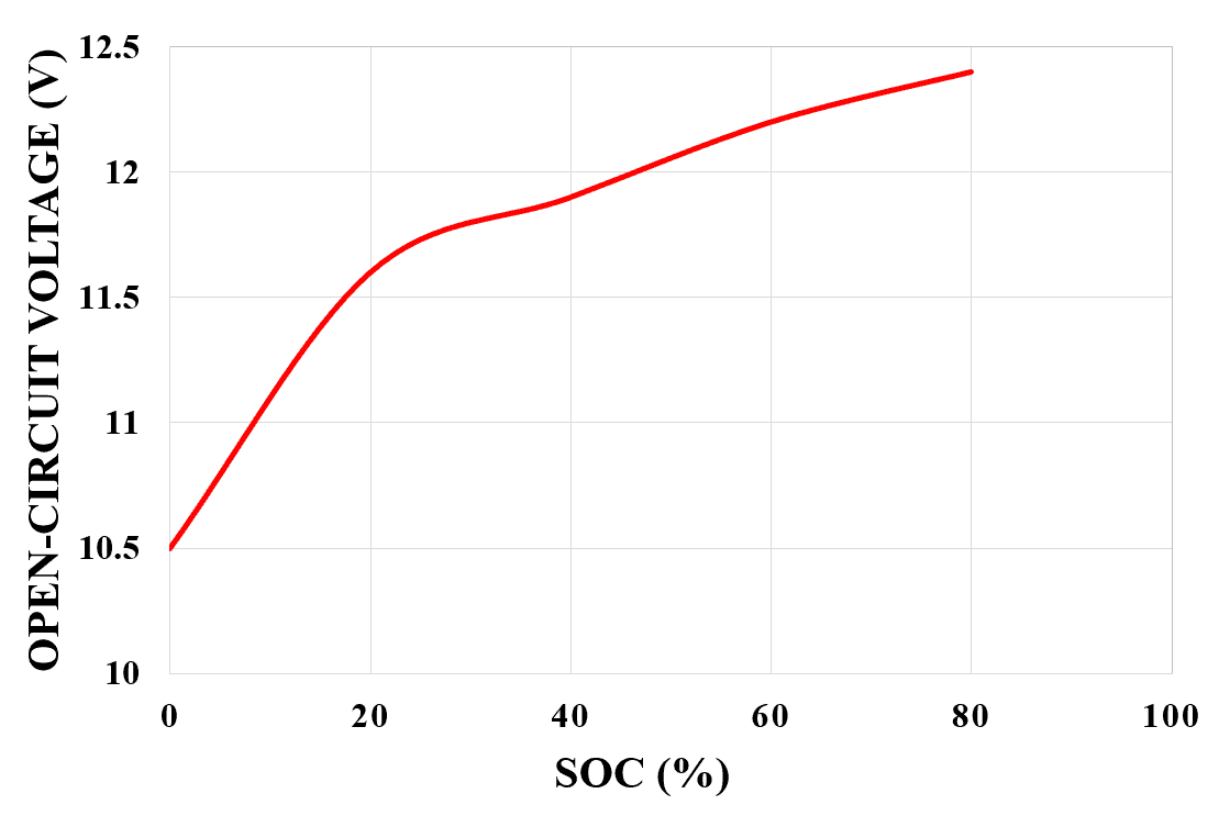
It is possible to measure the SOC of the battery by measuring the terminal voltage of the battery. As we know that the SOC of the battery decreases while it’s being used, the terminal voltage of the battery also decreases along with the SOC.
So higher the SOC higher will be its terminal voltage and the lower the SOC the lower will be its terminal voltage. The relationship between the open-circuit voltage and SOC (%) for a lead-acid battery is shown in figure 3 below.
C-rating
When current is drawn from the battery the terminal voltage of the battery is less as compared to when no current is drawn from the battery i.e. open-circuit voltage. This is because the battery voltage drops due to the internal resistance of the battery.
If the current drawn is larger then more will be the drop in the voltage due to its internal resistance and less will be the voltage that appears across the terminal of the battery. The charging and discharging of the battery at a high current rate is not safe.
The amount of the current discharged has an important role in the backup time of the battery. The battery discharges at a faster rate as we increase the load current, over-discharging the battery will result in a reduced life span and mechanical damage. The following figure 4 shows the discharge characteristics of the battery as a function of time.

The manufacturers provide the details of the maximum charging-discharging current and voltage for its long-lasting operation. A battery can be charged by constant voltage, constant current, or both constant voltage and current.
A typical lead-acid battery can be charged by any of the above methods. Proper charging and discharging of the battery will increase its life span. To charge them in an appropriate way a charge controller is used. Now to charge and discharge the battery properly using the charge controller the manufacturers provide the maximum charging and discharging current in terms of C-rating.
This C-rating specifies the amount of time that is to be taken to charge and discharge a given battery. The C-rating can be determined by dividing the storage capacity (Ah) by the number of hours taken to reach a 100 % SOC (i.e. fully charged battery) or time taken to reach the tolerable DOD limit. It can be mathematically expressed as follows;
C-rating (Amperes) = Storage Capacity (Ah) / Hours of fully charged or discharged time (t) ….. (8)
Now let us take some examples to understand the C-rating of the battery. If we have storage capacity C and the time for full charge or discharge is 10 hours then the C-rating can be written as C/10. Consider a battery of 200 Ah storage capacity. What would be its C-rating for 1, 2, 4, 6, 7, 8, 12, 50, and 100 hours of battery charging time?
Then using the equation of C-rating below;
- For 1 hour of charging time:
C-rating (Amperes) = Storage Capacity (Ah) / Hours of fully charged or discharged time (t)
C-rating (Amperes) = 200 Ah / 1 hour
C-rating (Amperes) = 200 A i.e. C/1
- For 2 hour of charging time:
C-rating (Amperes) = Storage Capacity (Ah) / Hours of fully charged or discharged time (t)
C-rating (Amperes) = 200 Ah / 2 hours
C-rating (Amperes) = 100 A i.e. C/2
(c) For 4 hour of charging time:
C-rating (Amperes) = Storage Capacity (Ah) / Hours of fully charged or discharged time (t)
C-rating (Amperes) = 200 Ah / 4 hours
C-rating (Amperes) = 50 A i.e. C/4
(d) For 6 hour of charging time:
C-rating (Amperes) = Storage Capacity (Ah) / Hours of fully charged or discharged time (t)
C-rating (Amperes) = 200 Ah / 6 hours
C-rating (Amperes) = 33.33 A i.e. C/6
(e) For 7 hour of charging time:
C-rating (Amperes) = Storage Capacity (Ah) / Hours of fully charged or discharged time (t)
C-rating (Amperes) = 200 Ah / 7 hours
C-rating (Amperes) = 28.57 A i.e. C/7
(f) For 8 hour of charging time:
C-rating (Amperes) = Storage Capacity (Ah) / Hours of fully charged or discharged time (t)
C-rating (Amperes) = 200 Ah / 8 hours
C-rating (Amperes) = 25 A i.e. C/8
(g) For 12 hour of charging time:
C-rating (Amperes) = Storage Capacity (Ah) / Hours of fully charged or discharged time (t)
C-rating (Amperes) = 200 Ah / 12 hours
C-rating (Amperes) = 16.66 A i.e. C/12
(h) For 50 hour of charging time:
C-rating (Amperes) = Storage Capacity (Ah) / Hours of fully charged or discharged time (t)
C-rating (Amperes) = 200 Ah / 50 hours
C-rating (Amperes) = 4 A i.e. C/50
(i) For 100 hour of charging time:
C-rating (Amperes) = Storage Capacity (Ah) / Hours of fully charged or discharged time (t)
C-rating (Amperes) = 200 Ah / 100 hours
C-rating (Amperes) = 2 A i.e. C/100a
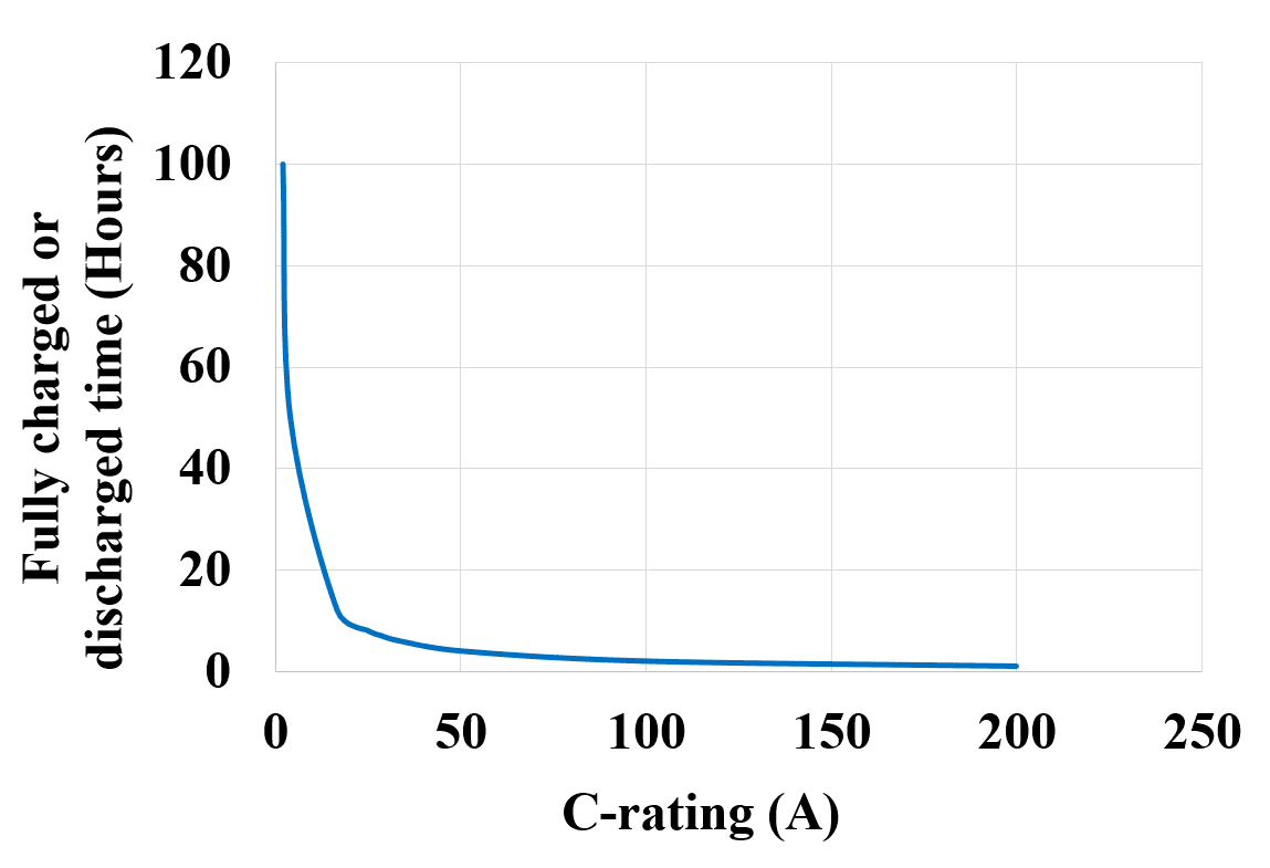
Now let us see a graph of C-rating (A) VS the hours of fully charged or discharged time (t) as shown in figure 5 below. It can be observed that the charging or discharging current i.e. the C-rating is lower for the higher number of hours, as the number of hours decreases the value of the C-rating increases.
It is not good to discharge a battery with a higher current unless the battery itself is designed for high current discharge. A C/4 battery should not be charged or discharged with a C/2 or C/12 rating as it would reduce its life span.
Related Posts:
- How to Design a Solar Photovoltaic Powered DC Water Pump?
- How to Wire Solar Panels & Batteries in Series-Parallel Connection?
Efficiency
The rechargeable batteries charging voltage is always greater than its discharging voltage. The charging voltage is the summation of voltage drop due to its internal resistance and the battery EMF. Mathematically it can be expressed as follows;
Charging voltage = E.M.F + VDrop ….. (9)
Whereas, the discharging voltage is the difference in voltage drop due to internal resistance and emf. Mathematically it can be expressed as follows;
Discharging voltage = E.M.F – VDrop ….. (10)
It is due to this internal resistance of the battery that the discharging energy is always less than the charging energy. Mathematically the charge transfer efficiency is given as;
Ampere-hour efficiency = [discharged energy (Ah) × 100 %] / Charging energy (Ah) ….. (11)
Another way is to calculate efficiency is by watt-hour efficiency.
Watt-hour efficiency = [discharged energy (Wh) × 100 %] / Charging energy (Wh) ….. (12)
The ampere-hour efficiency is more useful from the solar design point of view as it is used to determine the modules needed to charge a battery pack. Let us take an example to understand it more clearly.
A battery of 12 V is discharge and is now being charged for 6 hours with a current of 8 A, the average charging terminal voltage is around 15 V. Now when this battery is connected to a load it discharges a current of 4 A for 6 hours with the terminal voltage around 12 V. what is its ampere-hour efficiency?
Now to calculate the efficiency use the above equation as follows,
Ampere-hour efficiency = [discharged energy (Ah) × 100 %] / Charging energy (Ah)
Ampere-hour efficiency = [discharging current (A) × discharging time (h) × 100] / [Charging current (A) × Charging time (A)]
Ampere-hour efficiency = [4 × 6 ×100] / [8 × 6] = 50 %
Ampere-hour efficiency = 50 %
Operating Temperature
The temperature of the battery is one of the critical factors that affect the performance of the battery. The internal resistance of the battery and the chemical activity increases with the decrease in the temperature, this causes a decrease in the voltage and current of the battery.
The increase in the internal resistance of the battery results in the reduction of the terminal voltage. A typical lead-acid battery has an operating temperature range between -15oC to 60oC. The rating provided by the manufacturer is at the standard test condition having a temperature of 25oC.
If a battery of 200 Ah is discharged at 25oC it will give its maximum available capacity, but the same battery, if it is discharged at 15oC the available capacity of it would be less as compared to that when operated at 25oC. We can see this decrease in the capacity of the battery due to a decrease in temperature by measuring the SOC of the battery.
The SOC measured will be different at two different operating temperatures let’s say 20oC and 30oC. The SOC measured at 30oC will be higher as compared to that measured at 30oC, Due to high temperature the deterioration in the chemical activity can also reduce the charge capacity of the battery. Thus, the temperature of the battery is a crucial factor for designing a solar PV power plant.
Life Cycle
One cycle of the battery is one complete charge and discharge operation of the battery. The battery has limitations in its number of operations i.e. it can only be used for a finite number of charge-discharge cycles.
There is a slight decrease in the capacity of the battery due to several charge-discharge cycles. Thus, depending on the technology and the material used to manufacture the battery it can be used for a finite number of charge-discharge cycles.
This number of cycles that can be utilized is known as the life cycle of the battery. The battery’s life is considered to end when its capacity is decreased to 80% of its initial capacity. Let’s say that the battery is charge-discharged daily then we can say that one cycle is equal to one day and one year is equal to 365 charge-discharge cycles. This is how the life of the battery is given in terms of the number of cycles or number of years.
The chemical energy in the non-rechargeable battery can be converted into electrical energy once, hence non-rechargeable batteries have only one charge-discharge cycle. Typical batteries that are available in the market have a charge-discharge cycle ranging from 500 to 1500 cycles.
Care must be taken while discharging the battery because the DOD limit affects the life of the battery. If the battery is discharged below its DOD limit then the battery may get damaged while charging again. This will result in a reduced life span of the battery.
Increasing the DOD will reduce the life of the battery at a faster rate. For example, if we daily discharge a battery at 10% and charge again, it may continue to work for 5 years. But if we discharge the same battery every day at 30% and charge it again then it may continue to work for 3 years.
The DOD is different for different types of batteries and may also differ from manufacturer to manufacturer depending upon the quality of the material, construction of the two electrodes, and design adaptation.
Self-Discharge
When the battery has not been used for a long time the battery consumes some charge which is called self-discharge of the battery. This mainly happens due to the electrochemical process that takes place in the cell. It is similar to connecting a small load to the battery which results in self-discharge.
Ideally, the self-discharge of the battery should be zero and practically it should be as small as possible. To have a self-discharge as low as possible it is recommended to store the battery at a lower temperature. Besides this, the chemistry of the battery also determines the self-discharge of the battery.
Selection of a Battery
Many parameters are required for the selection of the battery for a particular application, such as voltage rating, current rating, life cycle, charge capacity rating and so on which differs from battery to battery and also from manufacturer to manufacturer.
In the case of a solar PV application selection of proper choice of battery from a vast variety of available batteries is challenging. This can be sorted out by knowing the minimum requirements, limitations, and conditions. A battery should be chosen according to the voltage and current requirement of the system to which the battery bank is to be connected. Every battery is designed to operate at a certain temperature which in general is about 25oC.
But we know that the ambient temperature could be more or less than the temperature at which the battery is meant to operate efficiently. With higher temperature, the battery can deliver a higher current but with lower temperature, the current delivered by the battery is less due to the slower chemical reaction in the battery.
Thus, the output current will be less than the design value. On the other hand, the battery at a higher temperature can deliver a higher current but it would reduce its life cycle. Therefore, the operating temperature of the battery is very significant while selecting a battery for a particular application.
Though modern batteries have a very low self-discharge rate. The life of the battery is directly affected by its self-discharge rate. The self-discharge can be observed in almost all batteries even if they are non-functioning. For an application where the constant function of the battery is required like the solar PV system, it is very important to consider the charge-discharge cycle of a battery.
Batteries with a large charge-discharge cycle are the most suitable for the application of a standalone PV system. Other factors that add up to the selection of the battery are the cost and availability of the batteries. Before choosing a battery, we need to make sure its availability in the market.
Unavailability of the chosen battery may cause users to select another one which may result in system redesign. Thus, batteries that are readily available in the market should be selected. The cost of a battery is based on its type and this may differ from manufacturer to manufacturer.
This also depends on the features of the battery system. Batteries which require very low maintenance are expensive. In some applications we may require to oversize the battery bank for the system to provide the required backup power at all conditions and times, this will add up to the cost. Making a battery-based system more reliable would increase the cost of the system. So, we have to choose between reliability and cost for a design of a particular application.
Related Posts:
- How to Wire Batteries in Series-Parallel to a Solar Panel?
- How to Wire Solar Panels in Series-Parallel Configuration?
Use of Battery in Solar PV Systems
It is desired that batteries used in the solar PV system should have low self-discharge, high storage capacity, rechargeable, deep discharge capacity, and convenience for service. For such a requirement the lead-acid batteries are widely used for the PV application.
They have a wide range of capacity, N-number of charge-discharge cycles, and a life span maximum of up to 3 years. Their replacement is simple and convenient and is also able to operate in a wide variety of temperature range (i.e., from -15oC to 60oC). The lead-acid batteries are classified into two categories:
- Liquid ventilated.
- Valve regulated lead-acid batteries.
The valve-regulated lead-acid batteries are further classified into two subcategories:
- Absorbed glass mat.
- Gel battery.
Liquid Ventilated: Widely applicable in the automobile industry. While utilization the battery produces hydrogen and oxygen due to its chemical reaction. Thus, this gas is required to be vented out. During the process of exhaustion, some of the water from the battery is lost and thus requires a refill, or failure to do so would result in the inappropriate function of the battery. Thus, they require a regular refill of water as important maintenance.
Valve Regulated Lead-acid: Unlike liquid ventilated batteries valve-regulated lead-acid batteries do not exit the water during their charging and discharging process. They are designed in such a way that the gases produced in the charging-discharging process are recombined within the battery without exhausting to produce water.
Such batteries are designed to have a regulated pressure inside. They are almost maintenance-free since no water is lost during their charging and discharging process and are well suitable to operate in any position upside, downside, etc and the acid won’t leak from the battery.
Absorbed glass mat has a fibrous silica glass mat which is used to suspend electrolyte which an electrolyte made up of semi-solid gel having some empty pockets that contribute towards the recombination of hydrogen during its charging which reduces the explosion risk.
Related Posts:
- How to Wire Batteries in Parallel to a Solar Panel and UPS?
- How to Wire Batteries in Series to a Solar Panel and UPS?
Battery Array
In a solar PV system, a standalone system, in particular, requires energy storage as compared to the grid-connected PV system. During the non-sunshine hours, the standalone system does not have any energy storage.
Thus, depending on the available battery parameters and the load energy requirement we require to connect batteries in series, parallel and mixed connections. Such a combination of N-number of batteries to meet the required energy demand is called a battery array. In the standalone PV application, we require higher voltage or higher current or sometimes both to meet our load requirement.
The number of batteries required to meet our load demand depends on the level of voltage and current we require at the battery array terminal. Just like a PV module when batteries are connected in series the voltage is higher than a single battery but the current remains the same.
Similarly, when the batteries are connected in parallel the current is higher than a single battery but the voltage remains the same. The total energy of the battery array is the summation of all battery energy connected in the array irrespective of the series and parallel connection of the batteries. For the series and parallel connection of the batteries, it is in the practice to connect batteries of the same rating.
Let us understand by considering a 12V, 200Ah battery. As we know the capacity of the battery in Ah is the product of the current and time. So, if we have a 12V, 200Ah battery, the amount of current given by the battery for 4 hours can be calculated as follows;
Current (A) = Capacity (Ah) / Discharge Duration (Hours) ….. (13)
Current (A) = 200 Ah / 4 Hours
Current (A) = 50 ampere.
Related Posts:
- Series, Parallel and Series-Parallel Connection of Batteries
- Series, Parallel & Series-Parallel Connection of Solar Panels
Installation and Commissioning of Battery Bank
This part can be categorized into two parts first is replacing the battery bank with a new one and the second is a complete installation and commissioning of the battery bank. To do with the first part we must have the entire infrastructure prepared which includes the battery charger, battery load, cables, etc. whereas, in the latter, we must have all those things selected or designed.
Now let us first look at the replacing of the old battery bank with a new one in which the infrastructure is ready and we have to replace the old battery bank. Following are the steps which are involved in this process:
- First of all, we need to isolate the battery from the existing charger and the load by switching the load to another battery and charger.
- Disconnecting the charger which is connected to the battery.
- Make sure you remove all the inter-row/cell connectors and cables.
- After this, it is important that we properly drain the electrolyte and store it safely.
- Replace the battery stand if it has been damaged.
- Arrange the battery stand in a room and assemble the new batteries on it.
- While placing the batteries on the stand the polarity of the batteries should be confirmed.
- Fill the new batteries with the electrolyte up to the level on the container.
- The acid takes some time to soak, allow up to 8 hours for the same.
- Prepare the battery for its first charging by making cable and inter-row/cell connections.
- Keep charging the battery at the initial rate till it reaches the voltage level of 2.35V to 2.45V.
- An hourly reading of the specific gravity, temperature, and voltage should be taken. Once cell voltage reaches the above-mentioned voltage level, decrease the charging current to 5% of the battery capacity. Here make sure the total Ah input remains the same.
- Make sure that the cell temperature does not exceed 50oC, if it does stop charging and wait till the temperature is down below 40oC, and then continue to charge at 5% of the battery capacity. Here again, make sure that the total Ah input remains the same.
- When we get a constant three consecutive hourly reading of the cell voltage and electrolyte specific gravity then cells are fully charged.
- Keep the cells unused for up to 4 hours. And when it comes to discharging isolate it from the charger.
- Now the battery discharging can be done. It can be done with water load or resistive load.
- Start discharging the battery as per the battery specifications mentioned by the manufacturer.
- While discharging record the cell voltage, temperature, and specific gravity.
- If any battery cell voltage has gone below 1.80V record it with the serial no. of that battery cell.
- Repeat steps 11 to 15 and record the cell voltage, temperature, and specific gravity of all cells while recharging.
- Now, repeat steps 16 to 20 during the second discharge.
- Adjust the specific gravity by adding the electrolyte if it is below 1200 in some cells during the second discharge.
- During final charging, repeat the steps from 11 to 15 and record specific gravity, cell temperature, and voltage during recharging. Once finished keep the batteries on float charging.
Related Post: A Complete Guide About Solar Panel Installation. Step by Step Procedure with Calculation & Diagrams
Inspection
Following are the important inspection of system components and conditions that are required to be carried out:
- Check if the battery’s health is in a good condition and is properly charged.
- When all the loads are disconnected the battery voltage across its terminal should have a reading above 12V.
- Make sure that the battery connections are clean and tight before testing the system.
- Check all the electrical connections, fuses, charge controllers, etc before beginning the test.
Diagnosis
- If the battery system is tested well but does not perform as per the expectation then the load connected to it exceeds the maximum power point resistance.
- There is also the possibility of the electric short and faulty voltage regulator.
- Failure to keep terminal tight and clean.
- Failure to interpret the battery’s in-built hydrometer.
- Not a sufficient ampere-hour charge rate of a drained battery.
- The battery is too old.
- In hot weather the internal chemical reaction increases which results in the self-discharge of the battery even if it is not connected to a load.
Testing the Battery Capacity
To conduct this test, we need a battery tester along with a digital multi-meter
- Adjust the multimeter selector switch to the DV position and turn the tester to an off position.
- Now connect the tester and multi-meter terminal leads to the positive terminal and negative to the negative terminal of the battery.
- Avoid connecting the multi-meter clips to the tester clips as this won’t give us the actual battery terminal voltage and would result in a measuring error. The multi-meter clips must connect to the battery post.
- Now turn the load control knob in the clockwise direction till the reading on the ammeter is half the value of the “cold cranking ampere” (The current delivered in the cold temperature is called “cold cranking ampere”, you will find cranking amps or cold-cranking amps on the battery details).
- Note the reading with the multi-meter, if it is 9.6V at 21oC, it means it has a good output capacity.
- If it is below 9.6V at 21oC and the battery is still fully charged, then the battery is damaged and requires a replacement. If not sure about its SOC, recharge it.
- Repeat the above steps once fully charged.
- If it is still below 9.6V then install a new one, if not it is good for service application.
- If we still find that it is completely discharged then check for loose connections, and proceed with the battery drain test.
Related Post: How to test a battery with Test meter?
Drain Testing
Note: Do not test the recently charged lead-acid battery as it would lead to injuries due to the explosive gases. And do not operate with equipment that draws more than 10 A of current as it will cause damage to the meter.
- Use an in-line ammeter between the battery positive and its cable.
- Switch the ammeter nobe to mA/A dc. Disconnect the battery terminals and connect the ammeter probes to the terminal.
- While reading the display isolate the circuit causing the current drain by pulling out one fuse at a time from the fuse junction panel and record the reading on the display. You will observe that the current reading will drop when the fuse on the bad circuit is pulled out.
- Now reinstall the fuse and see if there is any defective component in that circuit. The drain current reading observed should be less than 0.05A, if it exceeds this value that means some components are not shut off or are defective and are causing the current drain.
- If the load is not the reason for the drain current then remove the fuses from the interior fuse panel one by one until the source of the problem is discovered. If still unclear remove fuses one at a time at the power distribution to determine the problem.
- Related Post: Why Can’t We Store AC in Batteries instead of DC?
Detecting the Battery Fault
Detecting Electrical Faults in the Battery:
we can detect the electrical faults in the battery by using the multimeter. Note a warning here that we should not measure the current of the battery by directly connecting the multimeter to its terminals, since the multimeter has zero resistance, and connect directly to the battery terminal would cause a direct shorting of the battery terminals.
The typical voltage range of a 12 V lead-acid battery is 10.5 V to 13.5 V. If the multimeter measures a voltage outside the above-mentioned range then the battery is in a fault condition. If the measured voltage is below 10.5 V then the battery is over-discharged and if it is above 13.5 V then it is over-charged. Both the above conditions are not preferable and must be prevented by using suitable power electronics controllers to charge and discharge the batteries.
As stated earlier we cannot connect the multimeter directly to measure the current, to measure the current of the battery we must connect a load across it. Connect the positive probe of the multimeter to the positive end of the battery and negative to the load and complete the circuit by connecting the other terminal of the load to the negative end of the battery.
If for a fixed load the current is constant then the battery is working fine. But if the current reading observed is continuously varying and the load is also frequently fluctuating (e.g. a light bulb) then check for loose connections and overload conditions, if this is fine then the battery is at the fault and needs to be replaced.
The depth of discharge helps us determine how much percentage of the battery we can discharge if the battery does not provide sufficient depth of discharge then the battery is at fault.
Related Posts:
- What Happens if a Battery is Connected to the AC Supply?
- What Happens to the Battery with Reverse Polarity Wiring Connection?
Detecting Physical Faults in the Battery:
The battery must be checked for loose connections for leakage. Check for physical cracks on the outer body of the battery as if present it could result in the split of electrolyte from the battery. Replace the casing if any physical damage is found. Check if the external terminals are properly soldered to the internal connections for proper continuity.
Detecting Chemical Faults in the Battery:
The specific gravity is the concentration of electrolyte and the amount of water present in the electrolyte. Commonly this should be in between 1.1 and 1.4. we can use the value of specific gravity to measure the SOC of the battery and by doing that we can determine the chemical fault in the electrolyte.
Charging and Discharging of the Battery
The battery can be charged and discharged in many ways, like Constant current, Constant voltage, etc.
When the voltage of the battery is below a certain threshold, then there is a different method to charge the battery. When it is a cut-off point then we have to keep the voltage of the battery constant at the float value after charging. But in the charging method, it mainly depends upon the SOC of the battery.
First, charge the battery with a constant current till it reaches the float value, once the battery is charged up to its float value, the applied voltage is reduced slightly so the very little charge is supplied to the battery. This is known as the trickle charging phase.
The voltage applied to the lead-acid battery depends upon the gassing value of the voltage. As compared to the lead-acid battery the li-ion batteries have a better charging efficiency. Li-ion batteries are charged at constant current till the specified voltage has reached, the voltage is kept constant and the current reduces.
It stops charging if the current is down to 5% of the rated value. It is not much in a practice to apply the trickle charging phase in the li-ion battery.
Related Posts: How to Calculate the Battery Charging Time & Battery Charging Current – Example
Physical Maintenance of the Batteries
While doing physical maintenance of the battery first for sake of safety we must disconnect the battery from the electrical system. We must clean the terminals of the battery regularly. If not cleaned the copper sulfate gets deposited on the terminals of the battery.
Such an excess deposition should be removed periodically by cleaning it with a brush or even we can use polish paper. Depending on the usage of the battery this deposition takes place and clean should be done accordingly. Observation of the specific gravity is a significant part of the maintenance of the battery.
It can be observed lead-acid batteries which has a tubular deep discharge vented liquid. We can use a hydrometer to measure the specific gravity. It does the job of measuring the specific gravity of acid with respect to water. A battery hydrometer can also be used to measure the SOC of the battery by determining the density of sulfuric acid used as an electrolyte in the battery.
Related Posts:
- An introduction to Maximum Power Point Algorithms in PV Systems
- What is a Solar Charge Controller? Selecting the Right Size of MPPT & PWM Charge Controllers
- How to Design a Solar Photovoltaic Powered DC Water Pump?
- How to Wire Solar Panels & Batteries in Series-Parallel Connection?
- Solar Panel Wiring Diagram and Installation Tutorials
- Batteries Wiring Connections and Diagrams