Wind Power Plant – Wind Turbines, Generators, Site Selection & Scheme of Generation
How a Wind Power Plant Works? Classification of Wind Turbines and Generators, Site Selection & Schemes of Electric Generation
What is a Wind Power Plant?
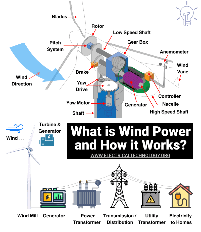
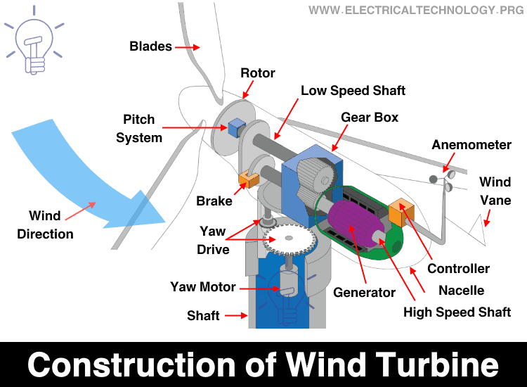
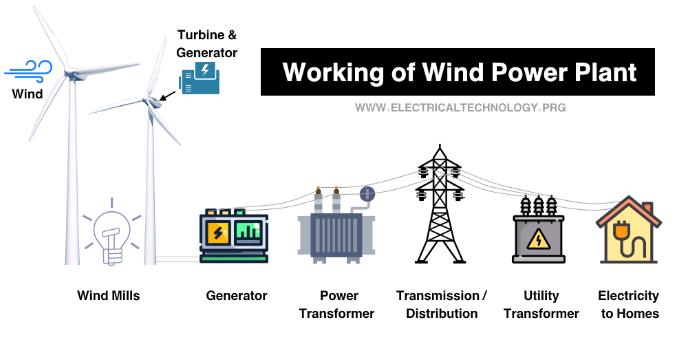
A wind power plant is also known as a wind farm or wind turbine. A wind power plant is a renewable source of electrical energy. The wind turbine is designed to use the speed and power of wind and convert it into electrical energy.
The wind power plant is widely used in the entire world. Because the wind is the best natural source that available in most places. The wind turbine can be operating between a wind speed of 14 km/hr to 90 km/hr.
A wind power plant is used to reduce the power deficit in a network. The electric power generated from the wind power plant varies with variations in wind velocity. But the advantage of a wind power plant is that the operating cost of this plant is less and it is a non-polluting source of electrical energy.
One single wind turbine is not sufficient to produce electrical energy in bulk amounts. Therefore, more than one wind turbine is placed at the location at which the wind is continually available. And that place is known as a wind farm. Generally, wind farms are located near the sea area.
Click image to enlarge
Classification of Wind Turbine
According to the orientation of the axis of the rotor, wind turbines are classified into two types;
- Horizontal axis
- Vertical axis
Horizontal Axis
Horizontal axis turbines are classified into two types;
- Propeller type
- Multiblade type
In a horizontal axis turbine, the orientation of the axis is kept along the horizontal axis. In a propeller-type turbine, a number of blades are three or less than three. And in a multiblade turbine, a greater number of blades are used.
The propeller-type turbine is mostly used turbine. The propeller-type wind turbines are mounted on top of the tower and the blade of this turbine is made up of an airfoil or aerofoil section. The below figure shows various types of propeller turbines.
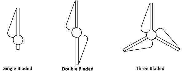
Two-blade turbines are the most cost-effective turbine. But in this condition, a yaw control system is required to mitigate vibration. This configuration is used for large units (2 MW to 3 MW) with suitable material and control systems.
A three-blade design is the most used and preferable design. Because the rotor is naturally balanced with a three-blade design. This configuration is used for a wide range of power generation (15 kW – 3 MW).
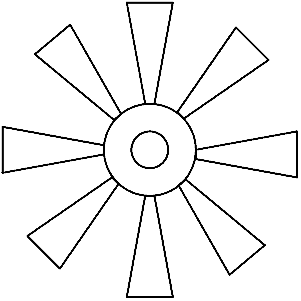
Multiblade turbines are used 12 to 20 blades made up of glass fiber reinforced plastic. The diameter of the multi-blade rotor varies from 2 m to 5 m. The multiblade turbine consists of curved sheet metal blades with inner and outer ends fixed with rims. The diagram of a multiblade turbine is as shown in the figure below.
Vertical Axis
Vertical axis wind turbine is classified into two types;
- Savonius type
- Darrieus type
In this type of wind turbine, the main rotor shaft is placed to transverse the wind and other accessories are placed at the base of the turbine.
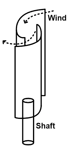
In savonius type wind turbine, a hollow elliptical cylinder is placed into two pieces. And each piece makes half of the vertical turbine fixed to a vertical axis. The shape of this rotor looks like the alphabet ‘S’. Therefore, savonius type rotor is also known as the S-type rotor. The figure of savonius type rotor is as shown in the below figure.
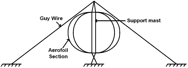
In darrieus type wind turbine, it consists of two or three blades. These blades are curved in shape and the shape of this blade is known as troposkein. The blades with aerofoil or airfoil cross-section are placed symmetrically on a vertical shaft. The darrieus type wind turbine is as shown in the figure below.
Performance of Wind Turbines
To estimate the performance of wind turbines, we need to consider the below parameters;
- Power co-efficient
- Tip speed ratio
- Solidity
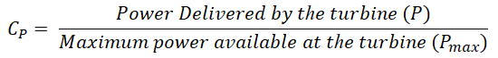
Power co-efficient
The power co-efficient defines as a ratio of power delivered by the rotor to the maximum power available in the wind turbine.
The maximum power available at the turbine (Pmax) is;

Where
- Ci = Incoming wind velocity
- A = Cross-section area of wind stream
- ρ = Density of air
Power delivered by a turbine (P) with an efficiency of 59.26%;
![]()
The actual efficiency of a wind turbine may be less due to friction losses into the rotor, gearing, and mechanical coupling losses in a generator. In an actual wind turbine, the efficiency is in the range of 35% to 44%.
Tip-speed ratio
The tip speed ratio defines as the ratio of blade tip speed to the free stream wind speed.
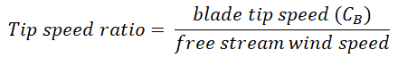
Blade tip speed is defined as;
CB = ωR
Where;
- ω = angular speed of the rotor
- R = radius of the tip of the rotor
This equation applies to the horizontal wind turbines. And in the case of the vertical wind turbine, the blade tip speed represents the peripheral speed at the middle of the blade length.
Solidity
Solidity is defined as the ratio of blade area to swept frontal area of the turbine.
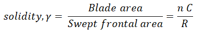
Where;
- C = mean chord length
- R = radius of rotor blades
- n = number of rotors blades
The above equation is for the horizontal wind turbine. For a vertical wind turbine, the above equation divides by 2. Higher the solidity ratio use drag force and turns at a slower speed. Lower the solidity ratio, use lift force and turn at higher speeds.
Site Selection of Wind Power Plant
The power produced by the wind turbine depends on the available wind speed. Therefore, the wind turbines are located at a place where persistent and strong wind is available. The wind varies daily. So, we need to analyze the data for a month or year.
To select the location for a wind turbine, the below-listed matters need to be considered;
- Wind speed
- Grid structure
- Distance
- Altitude of location
- Nature of ground
- Land cost
Wind speed
The power generated by the wind turbine depends on the cubic values of the velocity of the wind. Therefore, a small change in wind speed varies more generated power. We need to consider the average wind speed available for a particular location. For that, we required the data of wind speed for a year or month. After data analysis, we need to consider an average wind speed and select a site with a strong wind speed.
Grid structure
The power generated by the wind turbine is transferred to the load via a grid. The power output of the wind turbine depends on the wind speed and it fluctuates with respect to time. So, power output is also fluctuating with respect to time which gives poor power quality. Hence, the connection of wind turbines with the grid is the most important task.
Distance
The transmission line is used to connect the wind turbine with the substation or load center. If the distance of wind power plants is more, it will increase the transmission cost. Therefore, we need to select the site near the load center to reduce the transmission cost.
Altitude of location
At high altitude, the wind density is high which increase the output of wind turbine. In a place where the altitude is not available, the tower size is increased to get a high altitude. The height of the wind turbine is calculated from the sea level.
Nature of ground
To achieve high-density wind, the wind turbine is constructed at height. It requires a big and strong foundation to the ground. So, the nature of the ground is free from erosion and the place is free from land sliding problems.
Land cost
The initial cost of a wind turbine is very high because it uses costly material and very big construction of blades. The cost of land is also including in the capital cost. therefore, the cost of land must be as low as possible to reduce the capital cost. in most cases, the wind turbines are placed the non-useable lands.
- Related Post: What is Nuclear Power and How Nuclear Power Plant Works?
Schemes of Electric Generation
According to the speed and frequency, there are different schemes available for the electric generation by the wind turbine. These schemes are listed below.
- Constant speed constant frequency scheme
- Dual speed constant frequency scheme
- Variable speed constant frequency scheme
- Variable speed constant frequency with double output
- Variable speed variable frequency scheme
Constant Speed Constant Frequency Scheme
In this scheme, an induction generator or synchronous generator is used. The speed of the generator is equal to or more than the synchronous speed. The block diagram of this scheme is shown in the figure below.
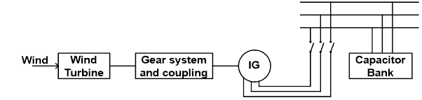
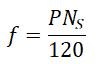
The induction motor starter is connected with the transmission grid. The induction motor runs more than synchronous speed. Hence, it behaves as an induction generator. And give constant frequency power to the transmission grid. The frequency of the induction generator is defined as;
The slip of the induction generator lies between 0 to 0.06. To avoid a large increase in speed, the induction motor should be operating below maximum torque. Compared to a synchronous generator, the operation of an induction generator is easy, simple in construction, less maintains, and economical. Therefore, the induction generator is more used in this scheme.
But while operating the induction generator, a capacitor or capacitor bank is required to avoid reactive power support in the transmission grid.
Dual Speed Constant Frequency Scheme
In this scheme, dual speed wind turbine is connected with a double winding transformer as shown in the figure below.
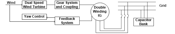
The induction generator is connected with 2 stator winding. These winding are made up of a different number of poles. Let say pole P1 and P2 (P1>P2). When wind speed is low, winding with P1 poles are connected with the system and according to that, the power is generated. When wind speed is high, winding with pole P2 is connected with the system and according to that, the power is generated.
Both times, the frequency of power remains the same. Similar to the above scheme, the capacitor is required to be connected with the transmission grid to avoid reactive power support on the transmission grid.
Variable Speed Constant Frequency Scheme
In this scheme, the DC transmission system is used. The synchronous generator is connected with the system and the output of three alternators or synchronous generator is converted into DC with the help of a rectifier. The connection diagram of this scheme is shown in the figure below.
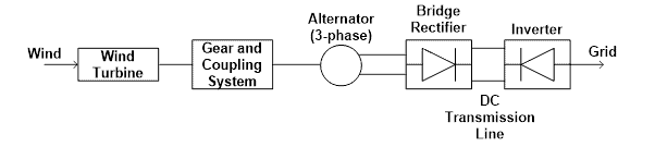
The DC output of the bridge rectifier is connected with the DC transmission line. And at the receiving end of the transmission line, the power is converted into AC with the help of an inverter. Again, this power is transferred to the transmission grid.
This type of scheme is also used in autonomous applications like a street light. It produces high power for both low and high wind speeds. This scheme is suitable for both vertical and horizontal axis turbines.
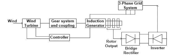
Variable Speed Constant Frequency with Double Output
In this scheme, the slip ring induction generator is used. This scheme is used to increase the power generating capacity of a wind turbine. The power is generated from both stator and rotor both. The output power generated at slip frequency is converted into power at line frequency using rectifier and inverter pair.
The output power from the rotor depends on the slip and speed. The operating speed range is between Ns to 2Ns and the slip lies between 0 to 1. The connection diagram of this scheme is shown in the figure below.
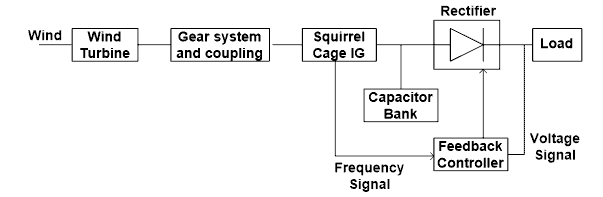
Variable Speed Variable Frequency Scheme
In this scheme, the synchronous generator is used to generate variable frequency power. For the excitation of the synchronous generator, a capacitor bank is used. The magnitude and frequency of the synchronous generator depend on the speed of the turbine, excitation of a capacitor, and load impedance.
The output of a generator is converted into DC power using a rectifier. To control and monitor the entire system, a feedback controller is used in the feedback loop. This type of scheme is useful in the application where the load is insensitive to a frequency like a heating load. The connection diagram of this scheme is shown in the figure below.
Generators used in Wind Power Plants
The generators are used in the wind power plant to convert the kinetic energy of wind into electrical energy. There is different generator used according to the power requirement. The below list shows the generators used in the wind power plant.
- Squirrel cage induction generator
- Wound rotor doubly fed induction generator
- Wound rotor synchronous generator
- Permanent magnet synchronous generator
Squirrel cage induction generator
The construction of the squirrel cage induction generator is simple and robust. The stator of the generator is connected to the grid with the help of an uncontrolled rectifier and a forced commuted PWM inverter. The connection diagram of the synchronous induction generator is as shown in the figure below.

The synchronous induction generator is directly connected with the wind turbine with the help of gear. The stator side converter is used to regulate the electromagnetic torque and supplies the reactive power. And the supply side converter is used to control real and reactive power flow to the transmission grid.
The stator of the induction generator is connected with the grid using back-to-back connected power electronics converters. The power converts are used to convert AC to DC and again DC to AC. The size of the converter depends on the power rating of a wind turbine.
The squirrel cage induction generator does not require brushes. Hence, the system requires less maintenance and the operation of the generator is easy and economical. A soft starter is required in the system to smooth operation with the grid. And the cost of the entire system is very high.
- Related Post: Why Power Plant Rated in MW and Not in kVA?
Wound rotor doubly fed induction generator
In this type of generator, the DC transmission link is used with the wind turbine. The figure of this scheme is as shown in the figure below.
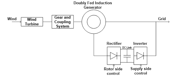
The output power from the induction generator is taken from both the stator and rotor. The stator winding is directly connected with the grid. And the rotor winding is connected with the grid via back-to-back converters. The rotor side converters are used to regulate the electromagnetic torque and regulate reactive power to maintain the excitation of the machine.
The main power transmits from stator winding. A small amount (20-30%) of power is transferred through the rotor. Hence, the cost of the converter is reduced. This scheme is used for high-power applications. This generator uses a slip ring induction generator that requires periodic maintenance.
Wound rotor synchronous generator
In this type of generator, the rotor winding is excited by a separate field system. This system is supplied by a separate DC source. The connection diagram of this system is shown in the figure below.
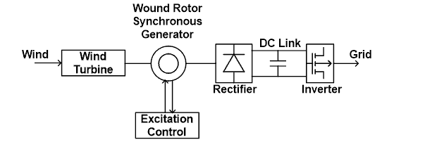
In this system, a DC transmission link is used to transfer the power from the wind turbine to the load center. To convert the power into AC to DC and DC to AC, back-to-back power converters are connected with the grid.
The power factor of the system and load characteristics can be controlled by controlling DC excitation. The stator winding is connected with the grid via four quadrants power converter. The stator-side converters are used to control the electromagnetic torque and the supply-side converter is used to control the real and reactive power.
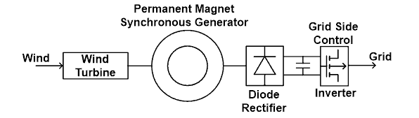
Permanent magnet synchronous generator
In this type of scheme, a permanent magnet synchronous generator is used with the wind turbine. The DC link is used to connect the wind turbine with the load center. Hence, this scheme required converter sets. In the below figure, the PWM rectifier is placed between the generator and DC link. And PWM inverter is connected to the grid.

In this method, the permeant magnet is used. And this will increase the cost of the system. Demagnetization occurs in the permanent magnet and the power factor cannot be controlled in this system.
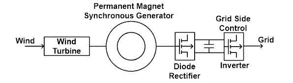
Instead of a PWM converter set, uncontrolled converters are also used in the system. This scheme is shown in the figure below.
In this scheme, the voltage and current are proportional to electromagnetic torque and rotor speed. Here, a boost converter and Voltage source inverter (VSI) is used. Boost converter controls the electromagnetic torque by controlling the DC voltage (by changing the switching ratio). The VSI is used to control the DC link voltage and input power factor.
The disadvantage of the diode rectifier is that amplitude and distortion increase in the current waveform. And it requires a bulky capacitor bank and the life of the capacitor bank is short.
To improve the performance of the wind turbine, back-to-back converts are used with the permanent magnet synchronous generator. The connection diagram of this system is shown in the figure below.
In this method, the reactive and real power can be controlled with the help of the PWM modulation technique. The use of this technique is costly and requires a sophisticated control system.
Related Posts:
- What is HVDC? High Voltage Direct Current Power Transmission
- Differences Between HVAC and HVDC Power Transmission
- Advantages of HVDC over HVAC Power Transmission
Advantages & Disadvantages of Wind Power Plant
Advantages
The advantages of a wind turbine are listed below.
- The wind is an infinite source of electrical energy.
- It is a cost-effective source as the running cost of the wind power plant is very less compared to a thermal power plant.
- It is environmentally friendly and does not require any carbon fuels. This plant help to reduce the carbon emission.
- The space required for the wind turbine is less compared to other power plants. In most of the cases, the wind turbines are placed on the seashore and in some cases, it is also installed in the sea to save space.
- A wind power plant can be a grid-connected plant or it can be directly used in the remote area where a grid is not possible to reach.
Disadvantages
The disadvantages of a wind turbine are listed below.
- The main disadvantage of a wind turbine is that it is inconsistent. The power developed by a wind turbine depends on the wind speed. And wind speed varies with time. According to that, the power output fluctuating. Therefore, it is very difficult to connect the wind turbine with a grid system. But, with the help of a power electronics converter, it is possible to connect the wind turbine with a grid. But it will increase the complexity and cost of the system.
- The capital cost to install a wind turbine is very high to build a construction and foundation.
- Wind turbines harm the birds.
- Site selection of wind turbines is difficult. It must be located at which the wind is constantly available.
- It is very difficult to transport heavy-spaced equipment of wind turbines at the site.
Related Posts:
- What is Electricity? Types, Sources & Generation of Electricity
- What is Electrical Power? Types of Electric Power and their Units
- Energy and Power Consumption Calculator – kWh Calculator
- FACTS – Flexible AC Transmission System – Types of FACTS Controllers & Devices
- Why Electric Power Transmission is Multiple of 11 i.e. 11kV, 22kV, 66kV etc?
- Corona Effect & Discharge in Transmission Lines & Power System
- Why Power Transmission Cables & Lines are Loose on Electric Poles & Transmission Towers?
- Difference between AC and DC Transmission System & Power Lines
- Design and Installation of EHV/EHV and EHV/HV Substations