How to Wire 48A Level 2 Dual Port EV Charging Station
Wiring Dual Port Level 2 EV Charging Station Using Two 60A or One 120A Breaker
Leviton’s Dual Port EV Charging Station
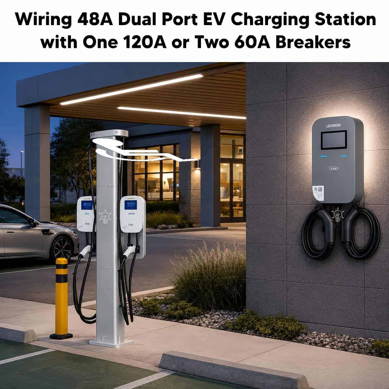
The Leviton EV48S-DP 48A Dual-Port Level 2 Electric Vehicle Charging Station is designed to simultaneously charge two electric vehicles from a single wall-mounted charging station. Each charging port delivers up to 48A of continuous charging current at 208–240V AC, making it ideal for commercial, workplace, fleet, multifamily, and public charging applications.
The charger supports two hardwired installation methods i.e. two independent 60A branch circuits (one dedicated circuit for each charging port) or one 120A branch circuit supplying both charging ports. In other words, the charger can be powered by either two individual 60A circuits or a single 120A circuit, depending on the installation requirements.
The charging station features two built-in SAE J1772 charging connectors, making it compatible with most electric vehicles. Tesla vehicles can also be charged using a compatible NACS (Tesla) to J1772 adapter.
With high-speed Level 2 AC charging, each charging port can deliver up to 47 miles (76 km) of driving range per hour of charging when operating at 48A – 240V.
In addition, the charging station is compatible with the AmpUp Charging Station Management Software (CSMS) platform for remote monitoring and management. It also supports RFID card authentication, allowing charging sessions to be enabled, controlled, and managed securely for authorized users.
Electrical Ratings & Specifications
- Name: Dual Port Level 2, 48A Electric Vehicle Charging Station – EV48S-DP
- Voltage: 208-240V AC – 60 Hz – Single-Phase
- Breaker Rating: 2 × 60A or 1 × 120A dedicated circuits
- Charging Current: 48A.
- Output Power: 2 × 11.6kW at 48A – 240V
- Charging Speed (est.): up to ~47 miles of range per hour
- GFCI / RCD: 20 mA CCID per UL 2231
- Wire Size: (Hardwire) = #1 AWG for 120A circuit and #3 AWG for 60A circuit (copper)
- Connector Type: SAE J1772 (Universal) or SAE J3400 – NACS Adapter (Tesla-style)
- Charging Cable: 2 × 25ft (7.6 m) Cable
- Connectivity: Cellular 4G, RFID authentication and computable with Charging Station Management Software (AmpUp)
- Listed: UL 2594, 2231-1, 2231-2, 2251, 62, 991, 1998, 840. NFPA 70 (NEC) Article 625 & CSA compliant with ISO 15118 and cUL
- Wiring Method: Hardwired – L1 (Hot 1), L2 (Hot 2) and Ground (EGC).
- Mounting: Wall mount or dual pedestal mount
- Enclosure: UL / NEMA Type 3R rated for Indoor / Outdoor Mounting
Mounting the Charger
Before installation and routing the conductors for both methods, confirm the service panel has adequate available capacity for the selected method (120A single circuit, or 60A x 2 = 120A combined if run as two circuits) using a proper load calculation per NEC Article 220 and 625.
Verify the wall or mounting surface can support the 37 lb (16.8 kg) charger and confirm mounting height of 48 inches in. (1200–1300 mm) from grade to the top of the mounting template, adjusting for ADA requirements where applicable.
Mount the charger per the wall-mount procedure (Torx key removes the two mounting-bracket screws; bracket is anchored to the wall with the four M6 expansion screws at the marked hole pattern; charger body then hangs on the bracket notch and is secured with the two retained screws at the bottom).
To do so:
- Install the mounting template approximately 48 inches above the finished floor.
- Mark and drill the mounting holes. Install the wall anchors and secure the mounting bracket.
- Lift the charger onto the bracket and fasten the retaining screws supplied with the charger.
- Install the cable entry depending on the wiring method (shown below):
- For individual branch circuits, install the supplied conduit fitting for multiple cables.
- Feed both branch circuits through the conduit fitting into the wiring compartment.
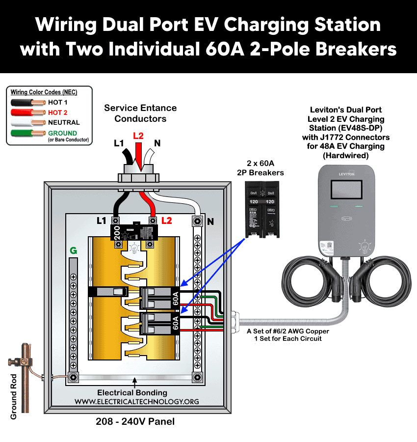
Method 1: Wiring with Two Individual 60A 2-Pole Breakers
The Leviton EV48S-DP Dual-Port level 2 electric vehicle charging station is designed to simultaneously charge two electric vehicles from a single wall-mounted charging station. Each charging port delivers up to 48A continuous output at 208–240V AC. This feature makes it suitable for commercial, workplace, fleet, multifamily, and public charging applications. The charger supports either two independent 60A branch circuits (one for each charging port) or one 120A branch circuit supplying both ports.
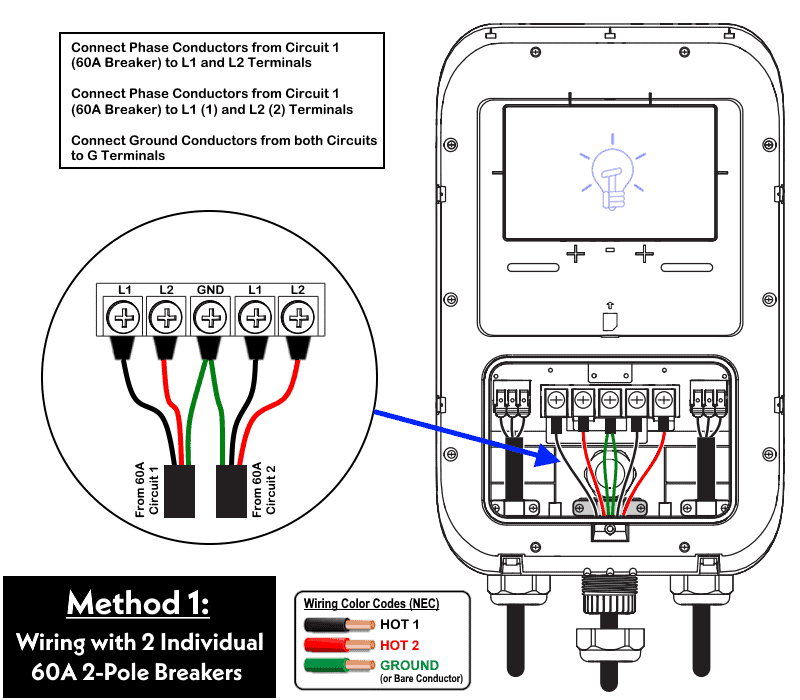
The charger terminal block provides two sets of line terminals which is marked L1/L2 (Port 1) and L1(1)/L2(2) (Port 2) plus a GND terminal (as shown i fig). In this method the two circuits remain electrically separate all the way to the terminal block i.e. no shorting terminals are used.
The following installation tutorial shows the dual-circuit method, where each charging port is supplied by its own dedicated 60A, 2-pole circuit breaker.
Click image or open in a new tab to enlarge
Step-by-Step Wiring Procedure
- Switch off the main breaker as well as both upstream 60A breakers to disconnect the power. Remove the cover of charger and panel to access the wiring terminal block and panel. If the breakers are not installed, make sure there are 4 empty slots in the panel. Snap over two 60A – 240V, 2-pole breakers on two adjacent busbars.
- Route Circuit 1’s phase conductors through the installed cable fitting and into the wiring compartment.
- Connect Circuit 1’s two phase (i.e. L1 (Hot 1) as black wire & L2 (Hot 2) as red wire) conductors from 1st 60A-2P breaker to the terminals marked L1 and L2.
- Route Circuit 2’s phase conductors through the fitting (using the second conduit run or the multi-cable conduit fitting).
- Connect Circuit 2’s two phase (hot) conductors from 2nd 60A 2-pole breaker to the terminals marked L1 (1) and L2 (2).
- Connect the equipment grounding conductors (Green wires or bare conductors) from both circuits to the terminal marked GND (as shown in wiring diagram)
- Torque all terminal screws to the manufacturer’s specified torque value (refer to the terminal block label)
- Secure conductors with the supplied cable clamp and self-tapping screws (if using the cable gland).
- Reinstall the wiring access panel and charger’s front cover. Snaps into place around the full perimeter, then reinstall the two retaining screws.
- Energize the charging station by turning ON circuit 1 and circuit 2 breakers. During startup, the charger performs a self-test. The LEDs illuminate in sequence before entering standby mode.
Click image or open in a new tab to enlarge
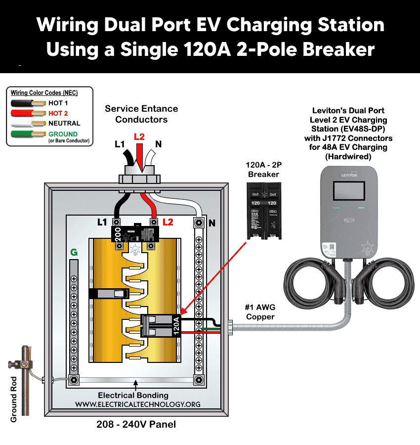
Method 2: Wiring Using a Single 120A 2-Pole Breaker
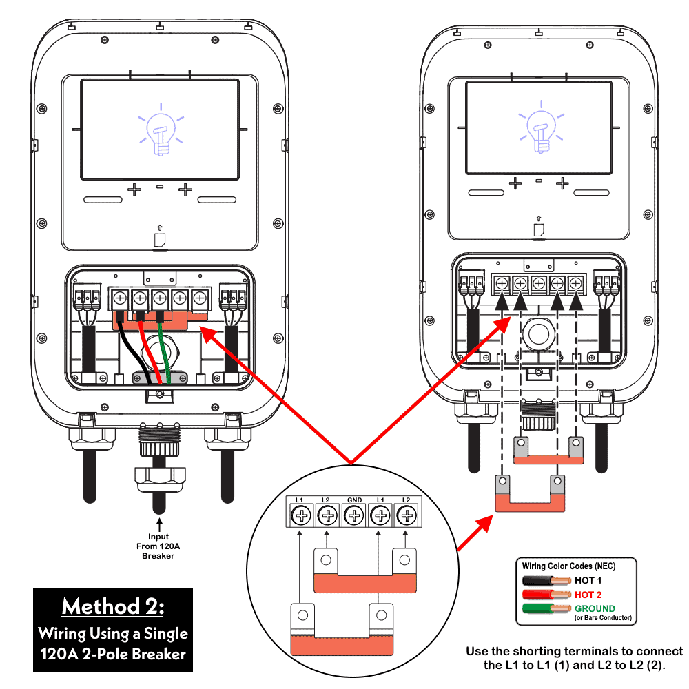
Unlike the dual-circuit installation described in method 1, this method supplies both 48A charging ports from a single 120A, 2-pole branch circuit. The EV48S-DP is internally designed to support this configuration by electrically connecting the two input terminal sets using the supplied shorting terminals (bus links).
Because a single circuit must feed both sets of line terminals, you will have to use the shorting terminals that bridge L1 to L1 (1) and L2 to L2 (2) at the terminal block. This internally parallels the two port terminal sets so one incoming circuit energizes both (as shown in the fig below).
When only one feeder supplies the charger, the L1 / L2 and L1 (1) / L2 (2) terminals must be electrically connected using the supplied shorting terminals before connecting the incoming conductors from 120A breaker. These factory-supplied links distribute power from the single branch circuit to both charging modules.
By doing so, this wiring configuration simplifies the installation by requiring only one feeder and one overcurrent protective device and allows both charging ports to operate from the same branch circuit.
Click image or open in a new tab to enlarge
Step-by-Step Wiring Procedure
- Confirm the charger cover and wiring access panel have been removed, and the upstream 120A breaker is OFF. If not already installed, snape a 2-Pole, 120A – 240V breaker in two empty slots on hot busbars.
- Install the supplied shorting terminal set which connects L1 to L1 (1) and L2 to L2 (2) as shown in fig.
- Route the single circuit’s two phase (L1 (Hot 1) as black wire and L2 (Hot 2) as red wire) conductors through the installed cable fitting into the wiring compartment.
- Connect the phase (hot) conductors to the terminals marked L1 and L2 (the shorting terminals will carry the connection through to L1 (1)/L2 (1) and out to both ports).
- Connect the single circuit’s equipment grounding conductor (green or bare conductor) to the terminal marked GND.
- Torque all terminal screws to the manufacturer’s specified value, including the shorting terminal hardware.
- If using the cable gland, secure the cable with the supplied cable clamp and self-tapping screws.
- Reinstall the wiring access panel and charger’s front cover to confirm it snaps into place around the full perimeter, then reinstall the two retaining screws.
- Restore power at the upstream breaker 120A breaker. The status light on unit should cycle Blue, Green, and Red on power-up, then settle to solid Blue (Standby) once initialization completes.
Click image or open in a new tab to enlarge
RFID Card Activation and Setting the Charger with AmpUp
To add the dual port charger in AmpUp charging station management software, activate the charger by following these steps:
- Visit the AmpUp activation page or scan the QR code on the green AmpUp sticker attached to the charger.
- Select the charger brand and click Continue.
- Review the checklist, then click Get Started.
- Enter your name, email address, and phone number.
- Select an existing site or create a new one.
- If creating a new site, enter the installation address, host contact information, and the electrical panel capacity limit.
- Follow the remaining on-screen instructions to complete the activation process.
Enabling or Disabling RFID Access Control
- To configure RFID access control on an EV Series Smart Home Charger:
Device → Settings → RFID Card
- From this menu, you can enable or disable RFID authentication for the charger.
Status Light Indicators
The LED indicator shows the operating status of all Leviton EV Series chargers. Refer to the table below for the meaning of each LED indication.
| Light Status | Indication |
| Blue, Green, Red (running clockwise) | Power On – startup sequence |
| Solid Blue | Standby |
| Solid Green | Charger connected to vehicle |
| Green, blinking | Waiting for authentication (swipe card) |
| Green, breathing | Charging in progress |
| Solid Green | Finished / stopped charging |
| Solid Yellow | Reservation charging |
| Yellow, blinking | Device unavailable |
| Yellow, breathing | OTA (firmware update) in progress |
| Solid Red | Fault |
Error & Fault Codes
The red status LED flashes a count corresponding to the fault type below, followed by a 3-second pause before repeating.
| Fault | Red Light Pattern | Recovery |
| Meter Fault | 1 flash + 3s pause | Auto recover |
| CP Fault | 2 flashes + 3s pause | Unplug connector to recover |
| UVP | 3 flashes + 3s pause | Auto recover |
| OVP | 4 flashes + 3s pause | Auto recover |
| OTP | 5 flashes + 3s pause | Auto recover |
| OCP | 6 flashes + 3s pause | Unplug connector to recover |
| Ground Fault | 7 flashes + 3s pause | Unplug connector to recover |
| Relay Fault | 8 flashes + 3s pause | Unplug connector to recover |
| RCD Abnormal | 9 flashes + 3s pause | Unplug connector to recover |
| RCD Self-Test Fault | 10 flashes + 3s pause | Reboot to recover |
| Relay Self-Test Fault | 11 flashes + 3s pause | Reboot to recover |
| Sensor Fault | 12 flashes + 3s pause | Check sensor or contact after-sales |
| Cable Fault | 13 flashes + 3s pause | Check cable or contact after-sales |
Instruction and Precautions
- Disconnect the power supply to de-energize the circuit before installation.
- Make sure the installation complies NEC Article 625 for EV charging, plus applicable Articles i.e. 110, 210, 220, 240, and 310. In addition, follow your local Authority Having Jurisdiction (AHJ) if applicable.
- Per NEC Article 625, the EV connector holster must be mounted between 18 in. (450 mm) and 4 ft (1.2 m) above floor level indoors, and at least 24 in. (600 mm) above grade outdoors.
- In regions with frequent thunderstorms, add surge protective devices (SPD) at the service panel.
- Install in accordance with the National Electrical Code (NEC), the Canadian Electrical Code (CEC), and all applicable local amendments for EVSE. Check with your local electrical inspector before starting.
- This equipment must be installed, adjusted, and serviced only by qualified and licensed electrician who is familiar with this type of equipment and its hazards.
- Failure to follow these instructions could result in death, personal injury, or property damage.
Disclaimer:
The author will not be liable for any losses, injuries, or damages from the display or use of this information or if you try any circuit in wrong format. So please! Be careful because it’s all about electricity and electricity is too dangerous. If you are unsure, contact a licensed electrician to do it according to the local area codes.
Resources:
EV Charger Wiring Series
- How to Wire AC Level 2 EV Smart Breaker Charger – 40A/32A
- How to Wire an EV Wall Charger – Hardwired and Plug-in
- How to Wire ChargePoint Home Flex Charger for Every EV
- How to Wire Smart Electric Vehicle Charging Station – 32A/80A
- How to Wire and Use Tesla Gen 3 Mobile Connector Charger
- How to Wire a Tesla Wall Connector & Universal EV Charger
Smart Devices Wiring Series
- How to Wire a Smart Switch in a 120/240V Load Center
- How to Wire 120/240V Smart Load Center with Smart Breakers
- How to Wire a Smart Breaker in a Smart 120/240V Panel
- How to Wire a Smart GFCI Breaker in a 120/240V Smart Panel
- How to Wire Smart AFCI/GFCI Breaker in a Smart Load Center
- How to Wire a 15A Wi-Fi Smart Outlet in a Smart Panel
- How to Wire 15A and 20A Wi-Fi Smart GFCI Outlets
- How to Wire Z-Wave Smart Switch, Dimmer & Fan Speed Controller
- How to Wire a Digital and Wi-Fi Smart LED Dimmer Switch
- How to Wire a Smart Switch Companion with a Smart Switch
- Wiring a Smart Dimmer Switch Companion with a Digital Dimmer
- How to Install a Wire-Free Smart Dimmer Anywhere Companion
- How to Wire Smart Scene Controller Switch
- How to Install a Wireless Smart Scene Switch
- How to Install a Wake and Sleep Wireless Smart Switch
- How to Wire a Smart Motion Sensing Dimmer Switch
- How to Wire a Combo Humidity Sensor & Fan Control with Light Switch
- How to Wire Humidity Sensor and Fan Control Switch
- How to Wire a Countdown Timer Switch – 15 Mins to 12Hrs
Wiring Standard GFCI & Breakers
- How to Wire a 1-Pole Breaker
- How to Wire a 2-Pole Breaker
- How to Wire a 3-Pole Breaker
- How to Wire a 1-Pole GFCI
- How to Wire a 2-Pole GFCI
- How to Wire a 3-Phase, 3-Pole GFCI
- How to Wire a Tandem Breaker
- How to Wire GFCI Circuit Breakers
- How to Wire an AFCI Breaker
Main Panels Wiring Tutorials
- How to Wire 120V/240V Main Panel? Breaker Box Installation
- How to Wire 120/240V Smart Load Center with Smart Breakers
- How to Wire 208V/120V, 1-Phase & 3-Phase Main Panel?
- How to Wire 240V, 208V & 120V, 1 & 3-Phase, High Leg Delta Main Panel?
- How to Wire 277V/480V, 1-Phase & 3-Phase Main Service Panel?
- How to Wire a Subpanel? Main Lug Installation for 120V/240V
- Single Phase Electrical Wiring Installation in Home according to NEC & IEC
- Three Phase Electrical Wiring Installation in Home – NEC & IEC
- How To Wire a Single Phase kWh Meter – 120V/240V
- How to Wire a Three-Phase Meter? 120/208/240/277/347/480/600V
- How to Wire Spa Panel for Hot Tub using 2-P GFCI & Breaker
Wiring General Outlets & GFCI/AFCI Receptacles
- How to Wire an Outlet Receptacle? Socket Outlet Wiring Diagrams
- How to wire a GFCI Outlet?
- How to Wire an AFCI Outlet?
- How to a Wire 3-Way Combination Switch and Grounded Outlet?
- How to Wire a 15A – 125V Outlet – NEMA 5-15 Receptacle
- How to Wire a 20A – 125V Outlet – NEMA 5-20 Receptacle
- How to Wire a 15A – 250V Outlet – NEMA 6-15 Receptacle
- How to Wire a 20A – 250V Outlet – NEMA 6-20 Receptacle
- How to Wire a 30A – 250V, NEMA 6-30 Receptacle
- How to Wire a 50A – 125/250V Outlet – NEMA 14-50 Receptacle for EVs
Sizing Breakers, Wires & Panels
- How to Size a Load Center, Panelboards and Distribution Board?
- How to Determine the Right Size Capacity of a Subpanel?
- How to Find the Right Wire Size for 100A Service 120V/240V Panel?
- How to Size a Circuit Breaker?
- How to Find the Proper Size of Wire & Cable In Metric & Imperial Systems
- How to Size a Breaker and Wires in AWG with EGC for Load?
- How to Size Service-Entrance Conductors and Feeder Cables?
- How to Size Feeder Conductors with Overcurrent Protection
- How to Size a Branch Circuit Conductors with Protection?
- How to Size Equipment Grounding Conductor (EGC)?
- How to Size Grounding Electrode Conductor (GEC)?
- How to Size Main Bonding Jumper (MBJ)?
- How to Size Motors FLC, HP, Voltage, Breaker Size and Wire Size
- What is the Correct Wire Size for 100A Breaker and Load?
- What is the Right Wire Size for 15A Breaker and Outlet?
- What is the Suitable Wire Size for 20A Breaker and Outlet?