How to Wire a Smart Motion Sensing Dimmer Switch
Installation of a Smart Motion Sensing Dimmer Switch with Neutral Wire
Smart Motion Sensing Dimmer Switch
A smart motion sensing dimmer switch is an advanced lighting control device that combines motion detection, automatic lighting control, and dimming functionality into a single wall switch. Unlike a standard light switch that requires manual operation, a smart motion sensing dimmer can automatically turn lights ON when it detects movement and switch them off when a room becomes unoccupied. This hands-free operation improves convenience, enhances comfort, and helps reduce unnecessary energy consumption.
These modern smart motion-sensing dimmer switches offer customizable light levels, ambient light detection, and smart-home connectivity. They can be used to adjust brightness and create the desired atmosphere, schedule lighting by time of day, and set occupancy or vacancy modes to suit your needs. With softer illumination during nighttime hours, they’re ideal for hallways, bathrooms, bedrooms, laundry rooms, garages, closets, and other frequently used spaces.
Another major advantage is integration with smart-home ecosystems and mobile apps. Through a smartphone app or voice assistant, you can monitor and control lighting from virtually anywhere. By combining motion sensing, dimming, scheduling, and remote control, these devices provide a practical, energy-efficient solution for modern residential lighting in smart home automation.
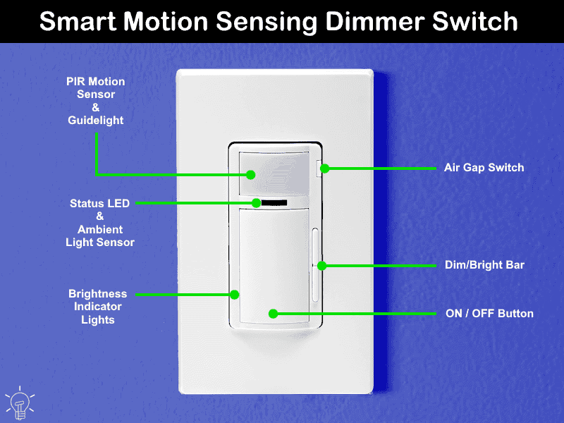
Rating & Features
- Name: Smart Motion Sensing Dimmer Switch – Decora Smart Wi-Fi – D2MSD
- Poles: Single-Pole, 3-Way & Multiway – With Neutral
- Voltage: 120V 1-Phase AC Supply – 60 Hz
- Current: 15A General & 5A LED/CFL or Electronic Ballast
- Wattage: 300W LED/CFL, 450W Incandescent/Halogen or 450VA Magnetic Low Voltage (MLV)
- Wire Size: #14 – #12AWG Copper
- Bridge / HUB: NO
- Coverage Area: Motion detection 180° (field of view) via PIR sensors up to 900 Sq. Ft
- Termination: Wired Leads
- Network: Wi-Fi – 802.11 b/g/n networks @ 2.4GHz, Bluetooth – v5.0 with WPA, WPA2, WPA3, or open security
- NEMA Listed: CSA / UL 1472, UL 773A Listed
- Range: 30 × 30 ft (≈ 9 x 9 meters)
- Compatibility: Amazon Alexa, Google Assistant (Hey Google / Google Home), Apple HomeKit/Siri, SmartThings, Matter, IFTTT, Schlage & My Leviton App (Android/iOS) to control up to 99 devices in 50 rooms.
Wiring a Smart Motion Sensing Dimmer Switch with Neutral
In the following wiring tutorial, we will demonstrate how to control a lighting point from anywhere through smart phone via a smart motion sensing dimmer switch. For automatic operation, it can be used as motion activated light control without touching the switch i.e. it automatically turns the lights ON (when someone enters the room). Similarly, the light automatically turns OFF when the occupant leaves the room.
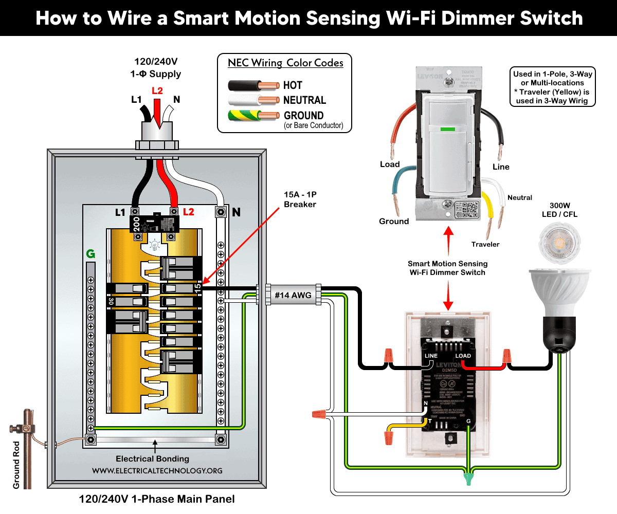
The following wiring diagram shows a smart motion-sensing dimmer switch (D2MSD) used to control a lighting point. The smart switch is connected through a 15A, 120V circuit breaker in a 120/240V breaker panel.
As shown in the wiring diagram, the smart switch is connected to the branch-circuit conductors as follows:
- The hot (black) wire from the circuit breaker is connected to the LINE terminal.
- The neutral (white) wire from the breaker panel is connected to the N (Neutral) terminal.
- The equipment grounding conductor (bare copper or green wire) from the panel is connected to the G (Ground) terminal.
- The load wire (black) leading to the light fixture is connected to the LOAD terminal (the switch’s built-in red wire).
Since the switch is controlling a single lighting load, the Traveler (T) terminal is not used and should be capped or pigtailed as specified by the manufacturer. The traveler terminal is intended for 3-way or multi-way switching applications when used with compatible smart switches or companion devices.
Click image or open in a new tab to enlarge
Setup, Troubleshoot and Reset
Setup
To place the device into setup mode, press and hold the ON/OFF button for 7 seconds until the status light turns amber, then release the button. The status light will begin flashing green, indicating that the device is now in setup mode.
To exit setup mode, repeat the same procedure: press and hold the ON/OFF button for 7 seconds while the device is in setup mode. The device will then return to normal operation.
Adding to the Network
For Leviton smart devices, use the My Leviton app with Leviton Decora Smart devices available on both the Google Play Store (Android) and Apple App Store (iOS).
After installation, Tap the “+” and select “add a device”, follow the on-screen instructions within the respective app to add and configure your smart switch. Once set up, you can control your lighting remotely and enjoy the convenience and peace of mind that comes with a connected smart lighting system.
Troubleshooting
The smart device status LED indicator table shows the different status of the device during setup, troubleshooting and maintenance.
Reset the Device
To restore the device to its factory default settings, press and hold the ON/OFF button for 14 seconds. After the first 7 seconds, the status light will turn amber. Continue holding the button. After an additional 7 seconds (14 seconds total), the status light will rapidly flash red and amber. Release the ON/OFF button. The device will then reset to its factory default settings.
Instructions & Precautions.
- Always disconnect the power supply by switching OFF the circuit breaker at the main service panel before performing any electrical work.
- Do not use this dimmer switch with electronic low-voltage (ELV) loads or motor-driven loads, such as fans, pumps, or other motor-operated equipment.
- Use copper conductors only. Aluminum wiring is not compatible with this device and should not be connected to the switch.
- Installing the device in a metal wall box or using a metal wall plate may reduce wireless (RF) signal performance and communication range.
- Do not install the switch directly above a heat source or in locations where hot or cold air drafts can blow directly onto the sensor. Because the motion sensor is sensitive to temperature changes, such conditions may result in false triggering or reduced detection performance.
- Smart devices are intended for indoor use only.
- If you are unsure about any part of the installation, consult a licensed electrician and ensure compliance with applicable local electrical codes.
Disclaimer:
- The author will not be liable for any losses, injuries, or damages from the display or use of this information or if you try any circuit in wrong format. So please! Be careful because it’s all about electricity and electricity is too dangerous. If you are unsure, contact a licensed electrician to do it according to the local area codes.
Resources:
Smart Devices Wiring Series
- How to Wire a Smart Switch in a 120/240V Load Center
- How to Wire 120/240V Smart Load Center with Smart Breakers
- How to Wire a Smart Breaker in a Smart 120/240V Panel
- How to Wire a Smart GFCI Breaker in a 120/240V Smart Panel
- How to Wire Smart AFCI/GFCI Breaker in a Smart Load Center
- How to Wire a 15A Wi-Fi Smart Outlet in a Smart Panel
- How to Wire 15A and 20A Wi-Fi Smart GFCI Outlets
- How to Wire Z-Wave Smart Switch, Dimmer & Fan Speed Controller
- How to Wire a Digital and Wi-Fi Smart LED Dimmer Switch
- How to Wire a Smart Switch Companion with a Smart Switch
- Wiring a Smart Dimmer Switch Companion with a Digital Dimmer
- How to Install a Wire-Free Smart Dimmer Anywhere Companion
- How to Wire Smart Scene Controller Switch
- How to Install a Wireless Smart Scene Switch
- How to Install a Wake and Sleep Wireless Smart Switch
- Howe to Wire Combo Humidity Sensor & Fan Control with Light Switch
Wiring Standard GFCI & Breakers
- How to Wire a 1-Pole Breaker
- How to Wire a 2-Pole Breaker
- How to Wire a 3-Pole Breaker
- How to Wire a 1-Pole GFCI
- How to Wire a 2-Pole GFCI
- How to Wire a 3-Phase, 3-Pole GFCI
- How to Wire a Tandem Breaker
- How to Wire GFCI Circuit Breakers
- How to Wire an AFCI Breaker
Wiring General Outlets & GFCI/AFCI Receptacles
- How to Wire an Outlet Receptacle? Socket Outlet Wiring Diagrams
- How to wire a GFCI Outlet?
- How to Wire an AFCI Outlet?
- How to a Wire 3-Way Combination Switch and Grounded Outlet?
- How to Wire a 15A – 125V Outlet – NEMA 5-15 Receptacle
- How to Wire a 20A – 125V Outlet – NEMA 5-20 Receptacle
- How to Wire a 15A – 250V Outlet – NEMA 6-15 Receptacle
- How to Wire a 20A – 250V Outlet – NEMA 6-20 Receptacle
- How to Wire a 50A – 125/250V Outlet – NEMA 14-50 Receptacle
Switches Wiring
- How to Wire Single Pole, Single Throw (SPST) as 2-Way Switch?
- How to Wire Single Pole, Double Throw (SPDT) as 3-Way Switch?
- How to Wire Double Pole, Single Throw Switch? Wiring DPST
- How to Wire Double Pole, Double Throw Switch? Wiring DPDT
- How to Wire Double Switch? 2-Gang, 1-Way Switch – IEC & NEC
- How to Wire 4-Way Switch (NEC) or Intermediate Switch as 3-Way (IEC)?
- How to Wire Auto & Manual Changeover & Transfer Switch – (1 & 3 Phase)
Sizing Breakers, Wires & Panels
- How to Size a Load Center, Panelboards and Distribution Board?
- How to Determine the Right Size Capacity of a Subpanel?
- How to Find the Right Wire Size for 100A Service 120V/240V Panel?
- How to Size a Circuit Breaker?
- How to Find the Proper Size of Wire & Cable In Metric & Imperial Systems
- How to Size a Breaker and Wires in AWG with EGC for Load?
- How to Size Service-Entrance Conductors and Feeder Cables?
- How to Size Feeder Conductors with Overcurrent Protection
- How to Size a Branch Circuit Conductors with Protection?
- How to Size Equipment Grounding Conductor (EGC)?
- How to Size Grounding Electrode Conductor (GEC)?
- How to Size Main Bonding Jumper (MBJ)?
- How to Size Motors FLC, HP, Voltage, Breaker Size and Wire Size
- What is the Correct Wire Size for 100A Breaker and Load?
- What is the Right Wire Size for 15A Breaker and Outlet?
- What is the Suitable Wire Size for 20A Breaker and Outlet?
Finding the Number of Breakers/Outlets in a Circuit
- How to Determine the Number of Circuit Breakers in a Panelboard?
- How to Find the Number of Outlets on a Single Circuit Breaker?
- How to Find Voltage & Ampere Rating of Switch, Plug, Outlet & Receptacle
- How to Calculate the Number of Fluorescent Lamps in a Final Sub Circuit?
- How to Calculate the Number of Incandescent Lamps in a Final Sub Circuit?
- How to Determine the Number of Lighting Branch Circuits?
- How to Determine the Number of Branch Circuits? – 3 Ways
- How to Find the Number of Lights on a Single Circuit Breaker?