How to Test a Capacitor using Digital and Analog Multimeter – 8 Methods
8 Methods to Check and Test a Capacitor using a Digital Multimeter (DMM) or an Analog Multimeter (AVO).
In most electrical and electronics troubleshooting and repair tasks, a common challenge is testing capacitors. This tutorial outlines eight methods with circuit diagrams to test a capacitor using multimeter and determine whether it is functioning properly, defective, shorted, or open.
Capacitors can be tested using either an analog multimeter (AVO meter: Ampere, Voltage, Ohm meter) or a digital multimeter to assess their condition and decide if they are in good working order or need replacement with a new one.
Note: To measure the exact capacitance value, you will need a multimeter (analog or digital) equipped with capacitance measurement capabilities
Below are eight (8) methods to check and test if a capacitor is Good, Defective, Open, Dead, or Shorted.
- Related Post: How to Measure Capacitance using Multimeter
Method 1.
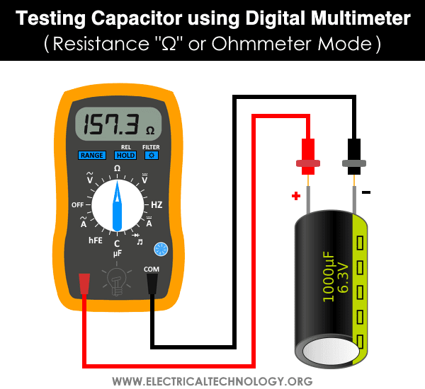
Test a Capacitor using Digital Multimeter – Resistance Mode
To test a capacitor by DMM (Digital Multimeter) in the Resistance “Ω” or Ohm mode, follow the steps given below.
- Make sure the capacitor is fully discharged.
- Set the meter on the Ohmic range (Set it at least on 1000 Ohm = 1kΩ).
- Connect the multimeter probes to the capacitor terminals (Negative to Negative and Positive to Positive).
- Digital multimeter will show some numbers for a second. Note the reading.
- And then immediately it will return to the OL (Open Line) or infinity “∞”. Every attempt of Step 2 will show the same result as shown in steps 4 and 5. It means that Capacitor is in Good Condition.
- If there is no Change, then Capacitor is dead.
Method 2.
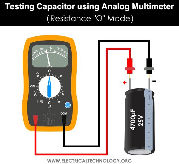
Check a Capacitor using Analog Multimeter – Ohm Mode
To check a capacitor by AVO (Ampere, Volt, Ohm Meter ) in the Resistance “Ω” or Ohm mode, follow the following steps.
- Make sure the suspected capacitor is fully discharged.
- Take an AVO meter.
- Rotate the knob on the analog meter to select the resistance “OHM” mode (Always, select the higher range of Ohms).
- Connect the Meter leads to the capacitor terminals. (COM to the “-Ve” and Positive to the “+Ve) terminals).
- Note the reading and compare with the following results.
- Short Capacitors: Shorted Capacitor will show very low resistance.
- Open Capacitors: An Open Capacitor will not show any movement (Deflection) on the OHM meter scale.
- Good Capacitors: Initially, it will show low resistance, and then gradually increases toward the infinite. It means that the capacitor is in good condition.
Method 3.
Checking Capacitor using Multimeter in the Capacitance Mode
Note: Testing a capacitor in the capacitance mode can only be performed if the analog or digital multimeter has the farad “Farad” of Capacitance “C” features. The function of capacitance mode in a multimeter can also be used to test the tiny capacitors. To do this, rotate the knob of the multimeter to the capacitance mode and follow the following basic instructions.
- Make sure the capacitor is fully discharged.
- Remove the capacitors from the circuit board.
- Now Select Capacitance “C” on the multimeter.
- Now connect the capacitor terminal to the multimeter leads.(Red to Positive and Black to Negative).
- If the reading is near to the actual value of the capacitor (i.e. the printed value on the Capacitor container box).
- Then the capacitor is in good condition. (Note that the reading may be less than the actual value of the capacitor (the rated value of capacitor due to the tolerance in ±10 or ±20 ).
- If you read a significantly lower capacitance or none at all, then the capacitor is dead and you should change it with a new one for proper operation.

- Related Post: How to Find the value of Ceramic Capacitors?
Method 4.
Testing a Capacitor By Simple Voltmeter
To apply this method on polar and nonpolar capacitors, you must know the value of nominal voltage of capacitors. The level of voltage is already printed on the nameplate of electrolytic capacitors. While there are specific codes printed on ceramic and SMD capacitors. You may follow this guide which shows how to read and find the value of ceramic and non-polarized capacitors with related codes printed on it.
Also, you can use the DC Voltage “V” or Volt Mode in the digital or analog multimeter to perform this test.
- Make sure to disconnect a single lead (no worries if Positive (long) or negative (short)) of the capacitor from circuit (You may fully disconnect as well if needed)
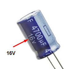
- Check the capacitor voltage rating printed on it (As shown in our below example where the voltage = 16V)
- Now charge this capacitor for a few second to the rated (not to the exact value but less than that i.e. charge a 16V capacitor with 9V battery. If the value of battery voltage is greater than the nominal voltage of the capacitor, it will damage or burst the capacitor.) voltage. Make sure to connect the positive (red) lead of the voltage source to the positive lead (long) of the capacitor and negative to negative. If you are not sure or unable to find the proper leads, here is the tutorial on how to find the negative and positive terminal of a capacitor.
- Set the value of voltmeter to the DC voltage and connect the Capacitor to the voltmeter by connecting the positive wire of the battery to the positive lead of the capacitor and negative to negative. You can use a digital or analog multimeter while selecting the DC voltage range for the same purpose.
- Note the initial voltage reading in the voltmeter. If it is close to the supplied voltage you gave to the capacitor, the Capacitor in in Good condition. If it shows far less reading, Capacitor is dead then. note that the voltmeter will show the reading for a very short time as the capacitor will discharge its stored volts in the voltmeter.

Note: The value of capacitor voltage should be less than the battery voltage. Otherwise, it will blast or burn the capacitor.
Method 5.
Test the Capacitor by Measuring the Value of Time Constant
We can find the value of a capacitor by measuring the Time Constant (TC or τ = Tau) if the value of capacitance of a capacitor is known in microfarad (symbolized µF) printed on it i.e. the capacitor is not blown and burnt at all.
In brief, the time taken by a capacitor to charge about 63.2% of the applied voltage when charges through a known value of resistor is called Time Constant of Capacitor (τ = Tau also known as RC time constant) and can be calculated via:
τ = R x C
Where:
- R = Value of known Resistor in Ohms
- C = Value of Capacitance
- τ = Tau (Time Constant)
For instance, if the supply voltage is 9V, then 63.2% of the supply voltage is around 5.7V. We will use a stopwatch and charge the capacitor until the value reaches 5.7V. Stop the watch and note the reading of time in seconds. For more details, check the example given below the instructions.
Now, let’s see how to find the value of a capacitor by measuring the Time Constant. (Note: An oscilloscope will do this better with precise value instead of multimeter.
- Make sure to disconnect as well as discharge the capacitor from the board.
- Connect a known value of resistance (e.g. 5-10kΩ Resistor) in series with the capacitor.
- Apply the known value of supply voltage. (e.g. 12V or 9V) to the capacitor connected in series with a 10kΩ resistor.
- Now, measure the time taken for the capacitor to charge about 63.2% of the applied voltage. For instance, if the supply voltage is 9V, then 63.2% of this is around 5.7V.
- From the value of the given resistor and measured time via a stopwatch, calculate the value of capacitance by Time Constant formula i.e. τ = Tau (Time Constant).
- Now compare the calculated value of capacitance with the value of capacitor printed to it.
- If they are the same or nearly equal with , The capacitor is in good condition. If you find a noticeable difference in both values, time to change the capacitor as it is not functioning well.

Example: Suppose, we are going to test a 16V, 470μF capacitor. If the supply voltage is 9V, then 5.7V is 63.2% of the supply voltage. We will connect the capacitor to the battery for charging and start the stopwatch. When the meter shows a 5.7V, we will stop the stopwatch. Suppose, the stopwatch shows 4.7 seconds of time duration.
Now, use the time constant τ = RC formula for measuring the capacitance i.e. C = τ / R
C = 4.7 seconds / 10kΩ
C = 0.47mF = 470μF
Now compare the calculated value of the capacitance with the value of the capacitor printed on it.
- If the calculated value is nearly equal or having a difference of ±10 to ±20 to the desired capacitor. It is a Good Capacitor.
- If the calculated value is far away with a noticeable difference, the capacitor is faulty.
- In our example, the calculated value is almost the same as the actual value of the capacitor. It means the capacitor is in good condition.
The discharge time can also be calculated. In this case, the time taken by the capacitor to discharge to 36.8% of the peak voltage can be measured.
Good to know: The time taken by a capacitor to discharge about 36.8% of the peak value of the applied voltage can be also measured. The discharge time can be used as the same in the formula to find the value of the capacitor.
Related Post: How to Test a Relay? Checking SSR & Coil Relays
Method 6.
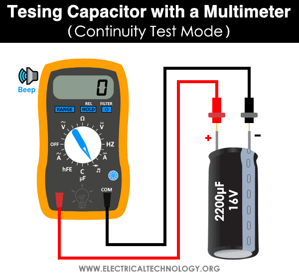
Test the Capacitor by Continuity Test Mode
In the DMM and AVO meter, the continuity test mode can also be used whether the capacitor is good, open or short. To do so, follow the simple instructions below.
- Disconnect the power supply and remove the capacitor from the circuit board.
- Fully discharge the capacitor using a resistor.
- Rotate the knob and set the multimeter in continuity test mode.
- Make a contact of the positive (RED) probe of the multimeter to the Anode (+) and Common (Black) probe to the Cathode (-) terminal of the capacitor.
- If the multimeter shows a sign of proper continuity (beep sound or LED light) and suddenly stops and shows an OL (open line). It means the capacitor is in good condition.
- If the multimeter doesn’t show a continuity sign with beep or led, it means the capacitor is open.
- If the multimeter LED lights ON and makes a continuous beep sound, it means the capacitor is short and it should be replaced with a new one.
Related Post: How to Test & Fix the Printed Circuit Board (PCB) Defects?
Method 7.
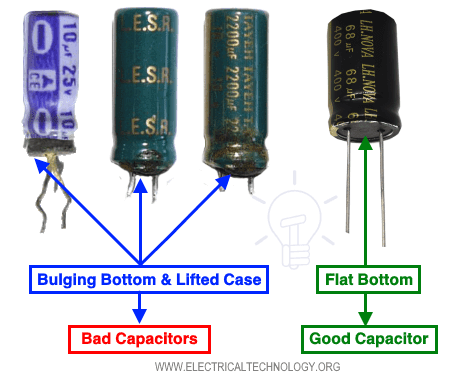
Test the Capacitor by Visual & Apparent Checking
It is the basic approach to determine the defective capacitor without a multimeter by observing the apparent signs appearing on it.
The capacitor is failed and damaged if you find any of the following conditions.
Bulging Top Vent of Capacitor
The top vent of the electrolytic capacitor in shape of K, T or X are the weak points made to release the pressure during the failure of a capacitor to avoid serious damage to the surrounding and any other components connected near to it.
If you find a bulging top of the capacitor, it is the electrolytic discharge (black, white, orange color which depends on the electrolytic material) i.e. the capacitor releases a gas pressure during failure and breaker the top vent of the capacitor.

Bulging Bottom and Lifted Case of Capacitor
If the produced gas pressure does not break the top vent of the capacitor during failure, it goes through the bottom and pushes the rubber which makes the bottom bulge and lifts the case.
Testing SMD and Ceramic Capacitors
If you find the following signs on ceramic or tiny SMD capacitors, they are faulty and need to be changed with the correct ones.
- Broken or cracks in the casing.
- Damaged or any sign of burnt casing.
- A hole in the casing.
- Broken terminals.

Method 8.
Traditional Method to Test & Check a Capacitor
Note: Not Recommended for everyone but professionals only. Please be careful to do this practice as it is dangerous. Make sure that you are a professional electrical engineer / electrician and you really know that you are doing something hazardous.
Please follow the safety precautions and warnings before applying this method. This is only applicable in an emergency (where replacing the capacitor with a proper value is important) and there are no other options to check the damaged capacitor. because serious damages may occur during this practice).
If you are not sure, (because serious damages may occur during this practice) follow the other options (1 – 7) as alternative methods to troubleshoot the capacitor.
Suppose you want to check the Capacitor (for example, fan capacitors, room air cooler capacitors or tinny capacitors in a circuit board / PCB etc.)
Warning & Safety Precautions for Testing a Capacitor by Method# 8.
For proper safety, use a 12 to 24V DC source in case of both polar and non polar capacitors with a 1kΩ~10kΩ, 5~50W resistor. The resistor should be connected in series with battery and capacitor positive terminals. This way, it will reduce the excessive current while charging the capacitor.
In case of absence of DC source (like batteries), the high rated capacitors (i.e. fan capacitors rated for. 3.5µF, 120, 230 or 400V) you may use 120-230V AC, but you have to connect a series of resistors (say 1kΩ~10kΩ, 5~50Watts) to connect between capacitor and 230V AC supply. This way, it will reduce the charging and discharging current. Here is the step by step tutorial on how you may check a capacitor by this method.
- Disconnect the suspected capacitor from the power supply or make sure at least one lead of the capacitor is disconnected from the PCB board.
- Make sure that the capacitor is fully discharged.
- Connect two separate leads to the capacitor terminals. (Optional)
- Now safely connect these leads to 24VDC or 230 V AC Supply for a very short period (about 1-4 Sec) [or for a short time where the Voltage rises to 63.2% of the Source Voltage] .
- Remove safety leads from the 24VDC/230V AC Supply.
- Now short the capacitor terminals (Please be careful to do that and make sure that you have worn safety goggles)
- If it makes a strong spark, then the capacitor is good.
- If it makes a weak or no spark at all, then it is a defective capacitor. You would have to change it immediately with a new one.
Note: Keep in mind that a polar capacitor should not be connected to the AC supply. On the other hand, a non-polar capacitor can be attached to the DC supply because, they are back to back electrolytic capacitors. As we know that capacitors block DC but let pass the AC but still it will charge with the DC supply source until it reaches the terminal voltage level. In short, non-polar capacitors can be operated on both AC and DC supplies while polar capacitors only operate on DC. For more details, check the previous important post on What Happens if We Connect a Polar Capacitor the Wrong Way?

Recourses and Related Tutorials:
- How to Check a Transistor by Multimeter (DMM+AVO) – NPN & PNP – 4 Ways
- How to Test a Battery using Test meter?
- How to Convert Capacitor μ-Farads to kVAR and Vice Versa? – For P.F Correction
- How to Test Earthing & Grounding System using a Light Bulb?
- How to Test Grounding / Earthing System using a Multimeter?
- How to Test and Measure the Ground Resistance using a Megger?
- How to Test the Earth Fault Loop Impedance – Various Methods
- How to Measure Frequency using Multimeter?
- How to Measure Power using Digital and Analog Multimeter?
- How to Measure Resistance using Digital & Analog Multimeter?
- How to Measure Voltage using Digital and Analog Multimeter?
- How to Measure Current using Digital and Analog Multimeter?
- How to Find the Value of Resistors for LED’s
- How to Find The value of Burnt Resistor (By three handy Methods)
- How to Find the value of SMD Resistors
- Even More DIY Electrical & EE How To Tutorials


EXCELLENT TUTORIAL
Thanks for Your appreciation.
Sir,
Thanks lot for sharing this hand on experience for checking capacitor.it’s really very very simple and easily understood.
Thanks again
Pls upload rest components testing also in same way.
Regards
Rajender
India
Useful information I mean.
How can I check a capacitor to see if it is bad
How can identify the tolerance of a capacitor?
The mathematical expression of how to come about the rang limit in which the capacitance fall in to.
Hi. Thanks for the information. How do l change direction of a capacitor start capacitor run induction motor.
Thank you. This is very useful information.
Welcome Dear..And bundle of thanks for appreciation..
just found this article that gives a far safer and good way to perform basic test on a capacitor forum.allaboutcircuits.com/showthread.php?t=5326<br the current article is very lacking in warnings and contains dangerous advice, I am an electronics engineer and as I said in my previous comment a professional would NEVER place a suspect cap across the mains like that
A professional would NEVER try option 1, if this was April 1st I could see this being published, <br />Capacitors DONOT store AC volts, to wack mains across an arbitrary capacitor is going to get someone KILLED, this option should be removed ASAP<br /><br />the whole theory is wrong…<br /><br />a capacitor rated at 250V AC does not mean it will store AC and capacitors are not rated for power
method 1 is incorrect. do not try this. you could get hurt and possibly fry your capacitor.
I agree that method 1 is very dangerous.
Really Dangerous. As a practicing engineer, I would never do this. Please edit the blog and delete point 1.
Also what does he mean by a weak spark vs a strong spark? What does a weak spark look like? What does a strong spark look like?
nice it is very use ful parameters
nice it is very use ful parameters
and i see it done by electician to check the capacitor
Wow that was good to know! This tutorial show how to use a digital multimeter (DMM), an indispensable tool that can use to diagnose circuits. The most basic things we measure are voltage and current. A multimeter is also great for some basic sanity checks and troubleshooting. Now this tester is also available which makes electrical testing easier with a wide range of multifunction testing accessories and ancillaries.Thanks
Thanks. Sir
It’s the science of alms
I agree. Connecting a suspect capacitor across mains is very dangerous. Capacitors used in
AC circuits are generally for delaying the AC cycles to mimic another phase. This second phase helps in turning AC motors. It also supplies a current boost to get the motor turning.
very good educational,thank a lot
Thank you on the capacitor info.
I truly find the information about the capacitor very useful. Thanks
how can use DMM to measure variable capacitor. thanks
Thank you very much for this perfect training
how to measure capictance for 1 hp motor or 70 watt fan, any formula? please help..
None of these methods will determine if a capacitor is good, although some of them will show you if a capacitor is bad. A capacitor has to be tested at it’s rated voltage and the current draw must meet the specs at the rated voltage.
Good tutorial.
Although most of this info is helpful, one of the issues I have found is the assumption that the capacitor isn’t breaking down under load. None of these tests would show this.
There is also another option to testing a capacitor (or inductor), if you have an o’scope available. It’s called an Octopus, and can be built using scrap parts. This site has a schematic: http://levysounddesign.blogspot.com/
Lastly, in my 40 years as an Electronics Tech, I’ve never heard of an Analog Multimeter referred to as an AVO Meter. Interesting.
With All Due Regards / Respects to everyone there!!
Good Day To All TOO!!
In late Sixties / Early Seventies, when I started my profession as Electronic Technician – we used to use Only & Only Analog Multimeter Namely “AVO” Meter – Marked as “AVO” Meter – Like “Fluke”, etc. being used these days.
“AVO” was a branded and Expensive Multimeter and Luckily I have One “AVO” Meter with me at my home in good working condition. At the moment I don;t have any picture of the meter at hand. This all was just for your info – Please.
Thanks for reading these line. – Keep Coming – Best of Luck.
In checking the value of a capacitor of nF range with a digital multimeter , should the board be powered up or not ???
Hello, every time i used to check website posts here early in the daylight, as i like to find out
more and more.
hello sir
can I check ht capacitor from this method and also charge from ht megger for checking.
ht capacitor fuse blown possible reasons
I heard along time ago that if you put the positive to the positive lead of the capacitor and the negative to the negative, it will show a charge. Flip the leads and it will show a discharge. Any truth to this?
Brilliant training ?????????
How do I learn more from you sir and your duration of study for student. Minimum months and maximum years sir.
Kindly reply to my email sir
Idiot. Get real
Thanks a lot for this information.
Item 1 regarding shorting the capacitor is extremely dangerous and should be deleted from this article. There is a severe danger of arc, severe damage of contacts, possible electrocution, etc.
There is another test using an ESR digital meter that usually uses high frequency and low voltages that will give a better representation if the capacitor is failing or not. Look into adding the ESR meter as a preferred method.
Can i charge a caoacitor with 220v ac
Very good information thanks
A good article, detailed introduction, easy to understand
“Method 1.
Traditional Method to test & check a capacitor (Not Recommended for everyone but professionals only)”
um… so why would a p[professional even be reading this?
In practically (method I) we shall check the capacitor by series circuit with 200 watt bulb charge the capacitor than short it.
Thank a lot.
if time constant is very low using the resistance 10k
how to find capacitance value for low value of capacitance ?
Thank you for this valuable and very useful information.
Please provide the information about High voltage polyster film capacitor testing
Wow, Really?? I came here to learn something about testing or evaluating whether a capacitor was good or bad. I will have to keep looking . I did learn something very important and that is not to perform any of the tests described in this article and to consult my electrician friends after reading any electrical how to article. Many thanks for the wake up call.
Cheers. John
Want to know About capacitors or how to test them and some of these methods are really and need to know how to test capacitors.
I hardly ever comment on posts, but as others have said, the first option is POTENTIALLY LETHAL and likely to cause a fire. DO NOT TRY IT.
Also, if you measure a capacitor and the value if significantly higher than it’s rated at then it’s probably leaking like a sieve. So that’s option 4 out the window…
I have two 10,000uF capacitors from my Hi-Fi that were leaking. They pass all (except the first!) of your tests because you’re only testing at DC.
What about physical checks? Quite often it’s clear that there is physical damage to a capacitor.