Scott-T Connection of Transformer
What is Scott Connection or Scott-T Transformer?
Scot Connection
Scott connection is a type of connection of transformer that used to get two-phase power supply from three-phase source or vice-versa. The Scott connection is also known as Scott-T Transformer. This method of transformer connection was invented by Charles F. Scott. So, after his name, this method is widely known as the Scott connection.
Related Post: Open Delta Connections of Transformers
Connection Diagram of Scott’s-T Connection
In Scott connection, two single-phase transformers are electrically connected but magnetically separated. One transformer is known as the main transformer and the second transformer is known as an auxiliary transformer. The auxiliary transformer is also termed a teaser transformer. The connection diagram of Scott’s connection is as shown in the figure below.
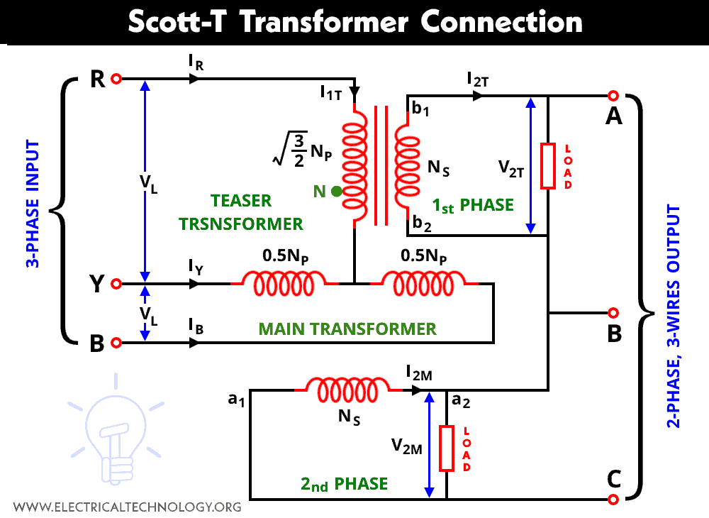
The primary winding of the main transformer is center-tapped at point D. And the two lines (Y and B) of a three-phase supply are connected to the primary winding of the main transformer. And the secondary winding of the main transformer is connected across points a1 and a2.
The primary winding of an auxiliary transformer is connected between the center-tapped point D and the remaining line terminal (phase R). And the secondary winding of an auxiliary transformer is connected between points b1 and b2.
The primary winding of the main transformer is center-tapped at equal parts. Therefore, the number of turns in part YD and BD is the same.
Related Posts:
- Open Circuit and Short Circuit Test of a Transformer
- Sumpner’s Test or Back-To-Back Test on Transformer
Phasor Diagram of Scott Transformer
The line voltages of a three-phase supply (VRY, VYB, and VBR) are equal in magnitude and 120-degree apart. The phasor diagram of supply voltage is shown in the figure below.

The phasor diagram of a three-phase supply can be drawn as an equivalent triangle. The magnitude of all line voltage is the same. Therefore,
VRY = VYB = VBR = VL
For calculation, we consider phasor YB as a reference phasor.
VYB = VL∠ + 0°
VRY = VL∠ + 120°
VBR = VL∠ – 120°
The center tapping point D divides primary winding into equal parts. Consider, the number of turns in the primary winding is NP. Therefore,

So, the voltage in portion YD and BD is the same and in phase with voltage VYB.

Now, we need to find the voltage of the primary winding of a teaser transformer (VRD). From the phasor diagram, we can write;
VRD = VRY + VYD

VRD = 0.866 VL ∠90°
The voltage given to the primary winding of a teaser transformer is 0.866 times of the main transformer. The voltage across a secondary winding of teaser transformer is V2T and the voltage across a secondary winding of the main transformer is V2M. Now, VRD is applied to the primary winding of a teaser transformer. Hence, the V2T leads V2M by 90˚. And the magnitude of both voltages is the same. The phasor diagram of Scott’s connection is shown in the figure below.

The voltage per turn must be the same in winding to create the same flux. Therefore, to make voltage per turn in a primary winding of the main and teaser transformer, the number of turns in a primary winding of the teaser transformer must be;
Therefore, the turns ratio in the teaser transformer is;

Hence, the secondary windings of each transformer have the same voltage magnitude with a 90˚ phase difference. So, it creates a balanced two-phase system.
Position of Neutral Point N
If the neutral point is available in a three-phase supply, tapping is provided on the primary teaser transformer. For example, taping is available at point N. Hence, the voltage across terminals RN is;

In the above equations, we have derived the value of the voltage between RD;

The voltage across point ND is;

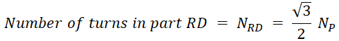
So, we have voltage across points RN, RD, and ND. For the same voltage turn ratio in these windings, the number of turns are chosen as;

From the above equation, we can derive the ratio of neutral point N divides the primary winding of teaser transformer as; RN:ND = 2:1.
Relationship of Input and Output Currents
The line current of the input three-phase supply is IR, IY, and IB. Here, we use two transformers and both transformers have primary and secondary winding. So, the current passes through the primary and secondary winding of the main and teaser transformer are as listed below.
- I1M = Primary current of the main transformer
- I2M = Secondary current of the main transformer
- I1T = Primary current of teaser transformer
- I2T = Secondary current of teaser transformer
From the connection diagram, the current that passes through the primary winding of the teaser transformer is line current IR. Therefore,
I1T = IR
The secondary winding of both transformers is identical. Hence, the magnitude of current that passes through both secondary winding is the same.
| I2M |= | I2T |
The balance MMF equation of teaser transformer is (neglecting effect of magnetizing current);
I1T NRD = I2T NS
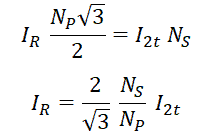
IR = 1.15 K I2T = I1T
Now, the balance MMF equation for the main transformer is;
I1M NYD – I1M NBD = I2M NS
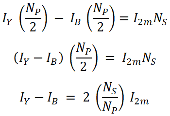
IY – IB = 2 K I2M
For balanced three-phase system;
IR + IY + IB = 0
IB = – IR – IY
IY – (- IR – IY = 2 K I2M
IY + IR + IY = 2 K I2M
IR + 2IY = 2 K I2M

Now, put the value of current IY into the equation of IB;

These equations of current are valid for balanced and unbalanced loads.
Applications of Scott Connection
The applications of Scott connection are listed below.
- This type of connection is used to connect a three-phase system with a two-phase system. And the power can be flow in both directions.
- The Scott connection is used to supply single-phase load (like electric trains) from a balanced three-phase supply.
- When the power is drawn from a three-phase supply, it is covert into a single-phase supply that uses for single-phase electric furnaces.
Related Posts:
- Why Transformer Rated In kVA, Not in KW?
- Applications of Transformers
- What is an Ideal Transformer?
- EMF Equation of a Transformer
- Equivalent Circuit of Electrical Transformer
- Parallel Operation of Single-Phase & Three-Phase Transformers
- Transformer’s Losses- Types of Energy Losses in a Transformer
- What is the Transformer’s Voltage Regulation?
- Transformer Efficiency, All day Efficiency & Condition for Maximum Efficiency
- The Dot Convention and Dot Notation in a Transformer Phasing
- Transformer Performance & Electrical Parameters
- Power Transformer Protection and Faults
- Transformers Fire Protection System – Causes, Types & Requirements
- Advantages of Three Phase Transformer over Single Phase Transformer.
- Difference Between Power Transformers and Distribution Transformers?
- Can We Replace a 110/220 Turns Transformer with 10/20 Turns?
- Electrical Transformer Symbols – Single Line Transformer Symbols
- Can We Operate a 60Hz Transformer on 50Hz Supply Source and Vice Versa?
- Which Transformer is More Efficient When Operates on 50Hz or 60Hz?
- Transformers (MCQs With Explanatory Answers)


