How to Wire a GFCI Combo Switch and Outlet?
Wiring and Installation of GFCI Switch/Outlet Commination with Single Pole Switch and 15A-120V Receptacle
a GFCI aka Ground-Fault Circuit Interrupter is a protective device designed to prevent electric shock. It operates by detecting ground faults and leakage currents between hot (line) and neutral. It is installed in outdoor and wet locations such as bathrooms, kitchens, laundries, and similar areas where GFCI protection is required by the NEC.
In our previous wiring tutorial, we demonstrated how to wire a GFCI outlet with both GFCI-protected and unprotected loads. A GFCI combo switch/outlet differs from a standard GFCI outlet in its configuration. A GFCI outlet contains two receptacles, whereas a GFCI combo device consists of one receptacle and one switch in a single unit. Expect the Line and Load terminals, the GFCI combo switch/outlet has two extra built-in wires for switch control on the back side. In this guide, we will explain how to use these terminals to control different loads or the GFCI-protected receptacle itself.
What is a GFCI Combo Switch/Outlet and How to Wire It?
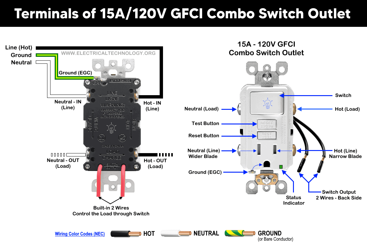
Before installation, it is essential to distinguish between a GFCI combo switch/outlet and a standard (ordinary) combo switch/outlet. In both devices, the line (live, hot, or phase) terminal corresponds to the narrow blade, while the neutral terminal corresponds to the wide blade.
In a GFCI combination switch and receptacle, both the single-pole switch and the receptacle are rated for 15A or 20A at 120V.
In a GFCI outlet, there is no break-away fin between the upper and lower line terminals, unlike a standard combo outlet. In a normal combo switch/outlet, the line conductor is connected to one line terminal, which is internally connected to the other line terminal via a break-away fin. The neutral conductor is connected to the wide blade terminal, and the load is controlled through the load terminals or optionally switch portion of the device as shown in below fig.
In today’s wiring tutorial, we will demonstrate how to wire and install a GFCI combo switch and outlet in residential applications. This includes protecting a light switch, a standard outlet (receptacle), lights, and additional switches, as well as using the switch in the GFCI combo device to control its own receptacle. You may also refer to our previous post for a basic explanation of the differences between GFCI and AFCI protection.
Wiring a GFCI Combo Switch Outlet with a Light Bulb
Click image or open in a new tab to enlarge
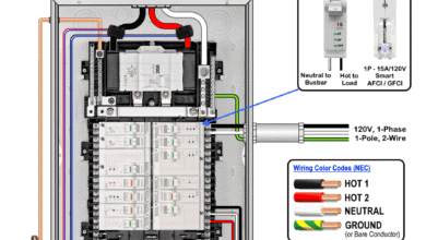
The following basic wiring diagram shows how to wire a 15A – 120V GFCI combo switch and outload for ground fault protection in a 120/240V main panel.

In the following wiring diagram, the connected load (as light bulb) is GFCI protected as it is controlled by the combo switch and connected to the load terminals of GFCI.
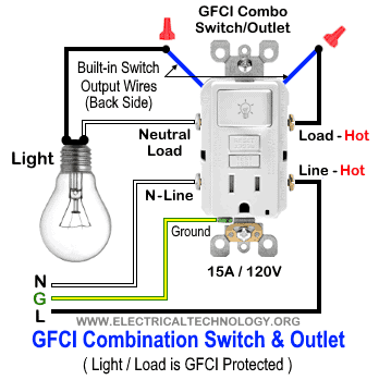
In this wiring diagram, the lamp is connected directly to the line terminals of the GFCI (i.e., directly to the main power supply). In this configuration, the light is controlled by the GFCI switch; however, it is not a GFCI-protected load.

Wiring a GFCI Switch/Outlet with a Standard Receptacle / Outlet
Same as the above wiring, the ordinary outlet / receptacle is GFCI protected and controlled by the switch as it has been connected the load terminals of GFCI.
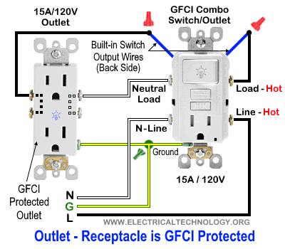
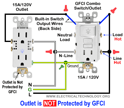
In the following wiring diagram, the standard outlet is controlled by the GFCI switch but is not GFCI-protected, as it is connected to the line terminals of the GFCI.
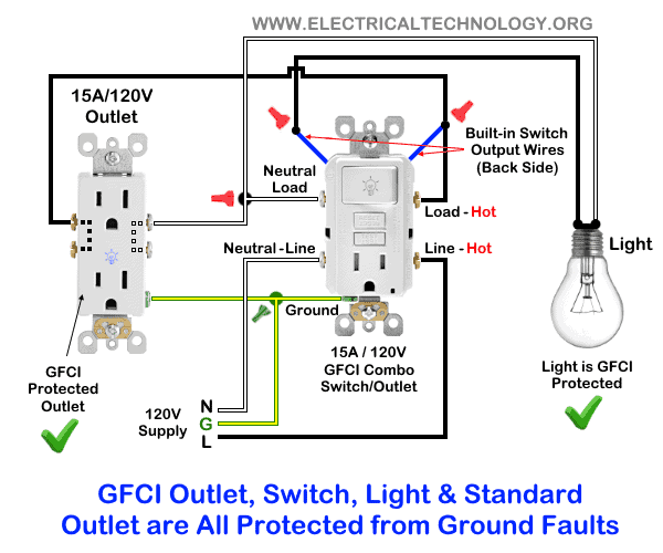
Wiring a GFCI Combo Switch/Outlet with Protected Light & Outlet Receptacle
In this special-case wiring diagram, both the light and the standard outlet are connected to the load terminals of the GFCI. The light’s ON/OFF operation is controlled by the GFCI switch, while the standard outlet is directly connected to the GFCI load terminals. In this configuration, both loads (the light fixture and the outlet, as well as any additional downstream loads connected to the outlet) are GFCI-protected.
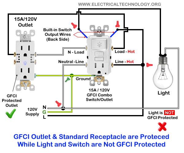
In the following wiring diagram, the standard outlet is connected to the load terminals of the GFCI, while the light bulb is connected to the line terminals of the GFCI. In this configuration, the outlet receptacle is GFCI-protected, whereas the light fixture is not GFCI-protected.
Wiring a Switched GFCI Combo Outlet
In this wiring tutorial, the switch in the GFCI combo switch/outlet is used to control the built-in receptacle. In other words, the outlet in the GFCI combo device can be turned ON or OFF using the upper switch.
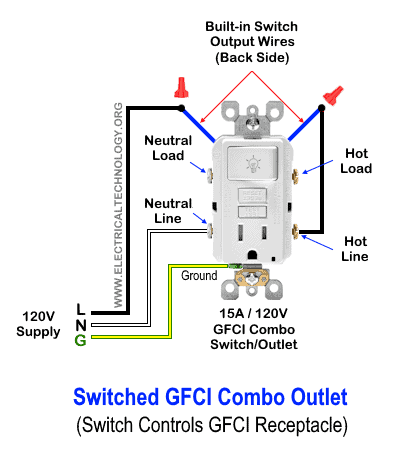
To achieve this, connect the upper built-in wire on the back of the GFCI combo device to the GFCI line terminal. Connect the second built-in wire to the incoming line (phase/live/hot) conductor. Finally, connect the ground terminal to the equipment grounding conductor (EGC) from the main panel.
With this wiring arrangement, the receptacle in the GFCI combo device can be switched ON and OFF using the built-in switch.
Instructions, Precautions & Codes
- Switch OFF the main circuit breaker to ensure the power supply is disconnected before wiring a GFCI outlet.
- GFCI protection is mandatory in outdoor and wet locations such as bathrooms, kitchens, garages, and similar areas, as required by NEC Article 210.8(A) for dwelling units.
- For a 15A, 120V circuit, use 14 AWG conductors. For a 20A circuit, use 12 AWG conductors, in accordance with NEC Table 310.16.
- Only 15A and 20A GFCI outlets rated for 120V are available. In other words, standard 240V GFCI outlets or receptacles do not exist.
- If GFCI protection is required for 240V circuits, use a 2-pole 240V GFCI circuit breaker instead.
- Use a switch with the appropriate voltage and current rating, along with a suitable wire size and a correctly rated breaker, based on the connected load.
- Maintain correct polarity by carefully identifying and connecting the line and load terminals of the GFCI device. Improper connections will result in incorrect or unsafe operation.
- Regular inspection and testing are recommended. Portable GFCI devices should be tested before each use.
- If you are unsure about the wiring or installation, contact a qualified and licensed electrician.
- The NEC wiring color codes have been used in this tutorial: black for hot, white for neutral, and green for the equipment grounding conductor (EGC). Always follow applicable local electrical codes.
The author assumes no responsibility for injuries, losses, or damages resulting from the use or misuse of this information. Exercise extreme caution as electricity is hazardous and improper handling can be dangerous.
Resources:
General Outlets and GFCI/AFCI Receptacles Wiring
- How to wire a GFCI Outlet?
- How to Wire GFCI Combo Switch and Outlet
- How to Wire an AFCI Outlet?
- How to Wire an AFCI Combo Switch
- How to Wire an Outlet Receptacle? Socket Outlet Wiring Diagrams
- How to a Wire 3-Way Combination Switch and Grounded Outlet?
- How to Wire Combo Switch and Outlet?
- How to Wire a 15A – 120V Outlet – NEMA 5-15 Receptacle
- How to Wire a 20A – 120V Outlet – NEMA 5-20 Receptacle
- How to Wire a 15A – 240V Outlet – NEMA 6-15 Receptacle
- How to Wire a 20A – 240V Outlet – NEMA 6-20 Receptacle
- How to Wire a 50A – 125/250V Outlet – NEMA 14-50 Receptacle
Standard & GFCI Breakers Wiring Installations
- How to Wire a 1-Pole Breaker
- How to Wire a 2-Pole Breaker
- How to Wire a 3-Phase, 3-Pole Breaker
- How to Wire a Tandem Breaker
- How to Wire a 1-Pole GFCI
- How to Wire a 2-Pole GFCI
- How to Wire a 3-Phase, 3-Pole GFCI Breaker
- How to Wire GFCI Circuit Breakers
- How to Wire an AFCI Breaker
Switches Wiring
- How to Wire Single Pole, Single Throw (SPST) as 2-Way Switch?
- How to Wire Single Pole, Double Throw (SPDT) as 3-Way Switch?
- How to Wire Double Pole, Single Throw Switch? Wiring DPST
- How to Wire Double Pole, Double Throw Switch? Wiring DPDT
- How to Wire Double Switch? 2-Gang, 1-Way Switch – IEC & NEC
- How to Wire 4-Way Switch (NEC) or Intermediate Switch as 3-Way (IEC)?
- How to Wire Auto & Manual Changeover & Transfer Switch – (1 & 3 Phase)
Finding the Number of Breakers/Outlets in a Circuit
- How to Determine the Number of Circuit Breakers in a Panelboard?
- How to Find the Number of Outlets on a Single Circuit Breaker?
- How to Find Voltage & Ampere Rating of Switch, Plug, Outlet & Receptacle
- How to Calculate the Number of Fluorescent Lamps in a Final Sub Circuit?
- How to Calculate the Number of Incandescent Lamps in a Final Sub Circuit?
- How to Determine the Number of Lighting Branch Circuits?
- How to Determine the Number of Branch Circuits? – 3 Ways
- How to Find the Number of Lights on a Single Circuit Breaker?
Main Panels Wiring Tutorials
- How to Wire 120V/240V Main Panel? Breaker Box Installation
- How to Wire 208V/120V, 1-Phase & 3-Phase Main Panel?
- How to Wire 240V, 208V & 120V, 1 & 3-Phase, High Leg Delta Main Panel?
- How to Wire 277V/480V, 1-Phase & 3-Phase Main Service Panel?
- How to Wire a Subpanel? Main Lug Installation for 120V/240V
- Single Phase Electrical Wiring Installation in Home according to NEC & IEC
- Three Phase Electrical Wiring Installation in Home – NEC & IEC
- How To Wire a Single Phase kWh Meter – 120V/240V
- How to Wire a Three-Phase Meter? 120/208/240/277/347/480/600V
Related Posts:
- Difference Between 1-Pole and 2-Pole Breakers – NEC & IEC
- Should GFCI Protection Be in the Main Panel or Receptacle?
- Can you use 15A Breaker on 20A Circuit and Vice Versa?
- Can I Use a 1-Phase Breaker on a 3-Phase Supply & Vice Versa?
- Can I Use a 240V Breaker on a 120V Circuit and Vice Versa?
- Can You use a 15A Outlet on a 20A Circuit and Vice Versa?
- How Does a Standard Breaker Respond to Electrical Fault?
- Why Doesn’t a Standard Breaker Protract Against Ground Faults?
- How Do GFCI and Standard Breakers Respond to Ground Faults?


Electrical and Electronics servicing Technology
I need reviews
Switch’s and more items are more important our electrical field
Why would you use such a weird color scheme for wiring diagrams? Why not match the wire colors to the already existing color code found In The real wires. This adds confusion to your content.
These instructions were much more helpful than those included with the GFCI receptacle I bought, so Thank you! (I agree with Greg: why not use default / standard colors in the diagram.)