How to Wire an Outlet Receptacle? Socket Outlet Wiring Diagrams
How to Wire and Install an Electrical Outlet Receptacle?
What is an Electrical Outlet, Receptacle or Socket Outlet?
Electrical Outlet (NEC) is also known as Receptacle and more commonly a Socket Outlet (IEC). According to NEC, an outlet is the point(s) in an electrical wiring system where current can be taken and utilize by electrical appliances and equipment by plugging them in it.
An outlet receptacle where one or more receptacle are installed or a supply contact device installed at the outlet to connect an electrical load through plugs and switches.
Ordinary outlet or standard outlet has screws (terminals) on both sides. The brass screws should be connected to the line (hot, live or phase) wire while the silver screws should be connected to the Neutral wire. In other words, the hot wire from main breaker should be connected to the narrow blade terminal where the Neutral wire should be connected to the wide blade terminal. The ground wire is connected to the ground terminal (mostly green color screw).
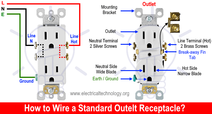
Keep in mind that the brass screws (for hot terminals) are electrically bounded to each other by a break way fin (tab) hence, connecting one brass screw to hot wire will feed the power to the second brass screw as well. In some case, you may remove the breakaway fin tab between the two brass screws (for hot wire) and split the outlet for other specific application (we will show in following wiring diagrams).
In today wiring tutorials, we will be showing that how to wire and install an electrical outlet in different ways.
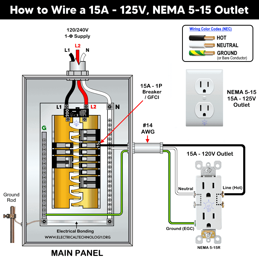
Wiring 15A, 120V Outlet
In this wiring, a 15A, 120V outlet (NEMA 5-15 receptacle) is connected to the 120V supply through hot, neutral and ground wire.
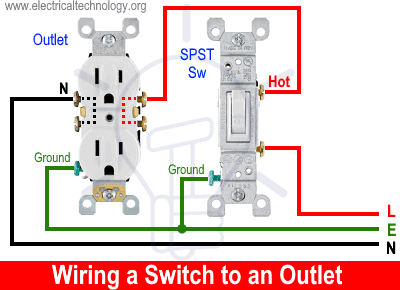
Wiring a Switch to an Outlet
In this wiring, a switch is added to to an existing outlet by removing the hot wire from outlet brass terminal and connected to the first terminal of switch. The second terminal of switch then connected back to the brass terminal of outlet. This way, the outlet is wired and controlled (ON/OFF) through the switch.
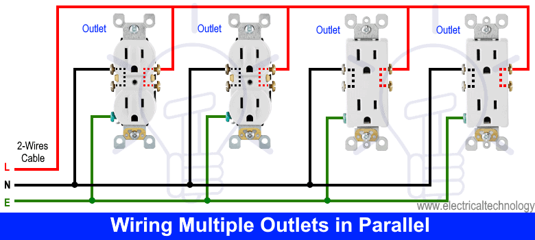
Wiring Multiple Outlets in Parallel
In this simple wiring diagram, multiple outlets have been connected in parallel. Each outlet is independent of each others as they are wired to separate cables. Keep in mind that series connection of outlet is against the NEC code (also it doesn’t make sense as if one of the outlet wires cuts or one faulty outlet will make the whole circuit useless) except GFCI and AFCI receptacles.
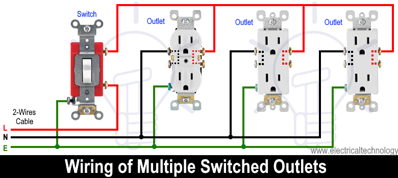
Wiring of Multiple Switched Outlets
The following wiring diagrams show that multiple outlets are wired to a single pole (SPST switch, one-way or two way in US) switch. As shown in the fig, the switch is firstly installed in the wiring the hot wire from switch feeds all the other parallel connected outlets hence, the outlet ON/OFF operation can be controlled through the switch.
Wiring a 15A Outlet with Light Switch
In this wiring, a light switch has been added to the existing outlet. The hot terminal of outlet is connected to the first terminal of switch and the second terminal of switch is connected to the lighting point. Finally, the neutral wire from outlet is connected to the light bulb.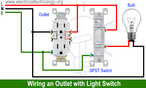
Wiring a Split Switched Outlet
In this wiring, the outlet operation has been split into two parts i.e. the upper outlet is controlled through the switch while the lower portion is always hot. To do this, simply remove the breakaway fin (tab) between the brass terminals (hot) as shown in fig. Connected the switch output (hot) to the upper brass terminal and the lower hot terminal should be connected to the switch input hot wire.
In simple words, a common hot wire should be connected to the first terminal of switch and lower hot terminal of outlet. The second terminal of switch (as hot) should be connected to the upper hot terminal of outlet. Finally, connect the neutral and ground wire accordingly as shown in fig below.

This way, the ON/OFF operation of upper portion (outlet) is controlled by the switch while the lower outlet is always hot and active.
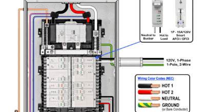
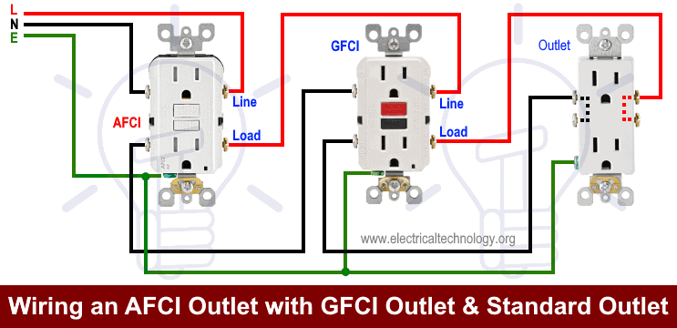
Wiring an AFCI and GFCI to the Outlet
In this wiring, the outlet is connected to the load terminals of GFCI where the GFCI is connected to the load terminal of AFCI. The standard outlet is both AFCI and GFCI protected. You can use both AFCI/GFCI protection in single unit instead of two outlets for AFCI and GFCI protection. This wiring is also known as series wiring of outlets which is only acceptable in case of AFCI or GFCI.
Wiring Dual Outlets from 240V Source for 120V
In this wiring, the first and 3rd outlet hot terminals are connected to the Line 2 (Blue) and the second and last outlets hot terminals are connected to the Line 1 (Red). The neutral is connected from the main breaker to all outlets neutral terminal. Ground wire is connected to the outlets as well as shown in the fig. This way, all the dual outlets are connected to the single line of 240V and can supply 120V to the appliances.

Wiring Combination of 120V and 240V Outlet
In this special wiring, a dual outlet is connected to both 120V and 240V where the upper portion provides 120V and the lower outlet provides 240V supply voltage. The special receptacle outlet 5031-I, 5842-I are used in these kind of wiring.
To do this, connect Line 1 and Line 2 to the lower hot terminals respectively. Connect the neutral and ground to the brass terminal and ground terminal respectively.

Keep in mind that you can’t run more than 20A at once from single outlet due to switch rating (Power = Voltage x Current) . For example, if a 15A air condition is connected to the upper 240V outlet and 10A, 120V heater to the lower terminal, the overall amperage is exceeding then than the switch rating. Alternatively, you can plug 100W bulbs to the lower 120V outlet, no matter if the upper outlet of 240V, 15A is operational for air condition as the total amperage is not exceeding the 20A for specified outlet.
Wiring 20A, 120V Outlet
In this wiring, a 20A, 120V outlet (NEMA 5-20 receptacle) is connected to the 120V supply through hot, neutral and ground wire.

Wiring 15A, 250V Outlet
15A-250V outlets are 2P, 3W, grounding receptacle without neutral connection. This way, both hots (Hot 1 and Hot 2) are connected to the brass terminals and the EGC (ground wire) is connected to the “G” terminal of the outlet. The following wiring diagrams illustrates how to wire a 15A – 250V (NEMA 6-15) outlet.

Wiring 20A, 250V Outlet
In this wiring, the line 1 (Hot 1) and line 2 (Hot 2) of 240V supply are connected to the brass terminals to the 20A-250V receptacle. As this is a 2-pole, 3-wire, grounding receptacle, hence, neutral is not needed. The ground wire is connected to the ground terminal.
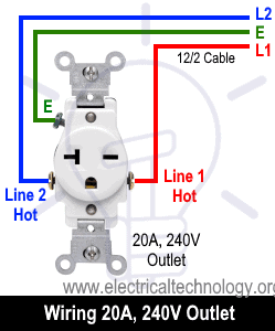
The following wiring diagrams shows how to wire a 20A – 250V (NEMA 6-20) outlet.

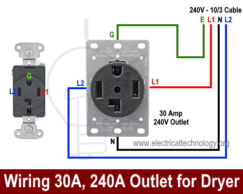
Wiring 30A, 240V Outlet for Dryer
In this wiring, a 30A, 240V outlet is wired for dryer where the neutral is needed as well. The Line 1, Line 2, Ground and Neutral wires are connected to the related terminals via 10 gauge 3 wires cable from separated breaker.
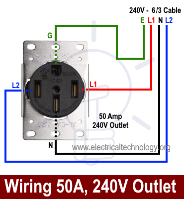
Wiring 50A, 240V Outlet
For high loads and amperage, the Line 1, Line 2, Neutral and ground is connected through a 6 gauge 3 wires cable from separate breaker to the related terminals of hot 1, hot 2, neutral and ground terminal as shown in fig below.
General Information about Electrical Outlets:
Note: We have used Red for Hot, Black for Neutral and Green for Ground for illustration purpose only. Follow your own area wiring color codes according to NEC, IEC etc.
- The brass screws should be connected to the Hot (line, live or phase) wire (Black, Brown or Red).
- The silver screws should be connected to the Neutral wire (White or Blue)
- The green screw should be connected to the ground / earth wire (Green/Yellow or naked)
- If there is no color coded screws on outlets, refer to the user manual or contact a licensed electrician.
- Neutral Wire is not required in 240V outlets wiring.
- If there are four prongs in an outlet, a Neutral wire is needed then and four wires from the breaker should be connected to the outlet i.e. 2 hot line as (Line 1 and Line 2), a Neutral and ground wire.
- Use the suitable voltage and ampere rating of switch with appropriate wire size and proper size MCB according to the load rating.
Precautions:
- Switch off the main circuit breaker to make sure the power supply is OFF before wiring an outlet.
- Contact the authorized and licensed electrician for outlet installation if you are not sure about the wiring diagrams.
- The author will not be liable for any losses, injuries, or damages from the display or use of this information or if you try any circuit in wrong format. So please! Be careful because it’s all about electricity and electricity is too dangerous.
Resources:
Related Wiring Tutorials
NEMA Family Outlets/Receptacle Wiring
NEMA 5 -Series
- How to Wire a 15A – 120V Outlet – NEMA 5-15 Receptacle
- How to Wire a 20A – 120V Outlet – NEMA 5-20 Receptacle
- How to Wire a 30A – 120V Outlet – NEMA 5-30 Receptacle
- How to Wire a 50A – 120V Outlet – NEMA 5-50 Receptacle
NEMA 6-Series
- How to Wire a 15A – 240V Outlet – NEMA 6-15 Receptacle
- How to Wire a 20A – 240V Outlet – NEMA 6-20 Receptacle
- How to Wire a 30A – 240V Outlet – NEMA 6-30 Receptacle
- How to Wire a 50A – 240V Outlet – NEMA 6-50 Receptacle
NEMA 10-Series
- How to Replace a 20A – 120/240V Outlet – NEMA 10-20R
- How to Replace a 30A – 120/240V Outlet – NEMA 10-30R
- How to Replace a 50A – 120/240V Outlet – NEMA 10-50R
NEMA 14-Series
- How to Wire a 20A – 125/250V Outlet – NEMA 14-20 Receptacle
- How to Wire a 30A – 125/250V Outlet – NEMA 14-30 Receptacle
- How to Wire a 50A – 125/250V Outlet – NEMA 14-50 Receptacle
- How to Wire a 60A – 125/250V Outlet – NEMA 14-60 Receptacle
NEMA General Outlets/Receptacle
- How to Replace a 15A – 125V Outlet – NEMA 1-15 Receptacle
- How to Replace a 20A – 250V Outlet – NEMA 2-20 Receptacle
- How to Wire a 30A – 125V Outlet – NEMA TT-30 Receptacle
General Wiring Installations:
- How to Size a Breaker and Wires in AWG with EGC for Load?
- How to Wire an Outlet Receptacle? Socket Outlet Wiring Diagrams
- How to a Wire 3-Way Combination Switch and Grounded Outlet?
- How to Wire Combo Switch and Outlet? – Switch/Outlet Combo Wiring Diagrams
- How to Wire 120V & 240V Main Panel? Breaker Box Installation
- How to Wire a Subpanel? Main Lug Installation for 120V/240V
- How to Wire 277V & 480V, 1-Phase & 3-Phase, Commercial Main Service Panel?
- How to Wire 240V Water Heater Thermostat – Non-Continuous?
- How to Wire 3-Phase Simultaneous Water Heater Thermostat?
- How to Wire Twin Timer for 120V/240V Circuits – ON/OFF Delay
- How to Wire ST01 Timer with Relay & Contactor for 120V/240V Motors?
- How to Wire Multifunction ON/OFF Delay Timer for 120V/240V Motors?
Switches Wiring
- How to Wire Single Pole, Single Throw (SPST) as 2-Way Switch?
- How to Wire Single Pole, Double Throw (SPDT) as 3-Way Switch?
- How to Wire Double Pole, Single Throw Switch? Wiring DPST
- How to Wire Double Pole, Double Throw Switch? Wiring DPDT
- How to Wire Double Switch? 2-Gang, 1-Way Switch – IEC & NEC
- How to Wire 4-Way Switch (NEC) or Intermediate Switch as 3-Way (IEC)?
GFCI/AFCI Breaker/Outlet Wiring
- How to Wire a GFCI Circuit Breaker?
- How to wire a GFCI Outlet?
- How to Wire GFCI Combo Switch and Outlet – GFCI Switch/Outlet
- How to Wire an AFCI Breaker?
- How to Wire an AFCI Outlet?
Related Posts:
- What is the Suitable Wire Size for 20A Breaker and Outlet?
- What is the Difference Between 15-Amp and 20-Amp Outlet?
- Difference Between Socket, Outlet and Receptacle
- Difference Between NEMA 14-50 Standard Vs EV Receptacle
- How to Find the Number of Outlets on a Single Circuit Breaker?
- How to Find Voltage & Ampere Rating of Switch, Plug, Outlet & Receptacle
- Can you use 15A Breaker on 20A Circuit and Vice Versa?
- Can You use a 15A Outlet on a 20A Circuit and Vice Versa?
- Ground Terminal Up or Down: Which Way Should Outlets Face?
- What Do the Green Dot or Orange Triangle Outlets Mean?
- What Do the Different Colors of Electrical Outlets Indicate?
- Why are Outlets and Receptacles in Hospitals Upside Down?
- How to Size a Load Center, Panelboards and Distribution Board?
- How to Determine the Number of Circuit Breakers in a Panelboard?
- How to Find the Proper Size of Circuit Breaker? Breaker Size Calculator & Examples
- How to Find The Suitable Size of Cable & Wire for Electrical Wiring Installation?
- Why is the Neutral Prong or Slot Wider on a Plug or Outlet?
- What Will Happen If You Connect a Male-to-Male Plug Between Outlets