Wiring Combo Humidity Sensor & Fan Control with Light Switch
How to Wire a Combination Humidity Sensor and Fan Controller with Light Switch
Combo Humidity Sensor & Fan Control with Light Switch
A humidity sensor and fan control with light switch is a combination single-pole device designed to automatically control a ventilation fan and a light fixture to reduce excess humidity in areas such as bathrooms, basements, laundry rooms, and spas.
This combination humidity-sensing fan control automatically detects elevated moisture levels in the air and activates the ventilation or exhaust fan to reduce condensation. By removing excess humidity, it helps prevent mold and mildew growth while reducing energy consumption through automatic fan operation. In other words, the fan runs only when needed.
The device uses a microprocessor combined with advanced digital sensing technology to continuously monitor and regulate humidity levels in areas of the home that are prone to condensation and mold.
The combination switch can be easily wired and installed in new construction or as a replacement for an existing single-pole switch. Depending on the model, it can be installed with or without a neutral conductor. The switch is compatible with incandescent, LED, CFL, ELV, and MLV lighting loads.
These devices help improve indoor air quality and support compliance with building codes and standards such as the 2019 and 2022 CALGreen Standards (Part II), ASHRAE Standard 62.2, and California Title 24 (Part 6).
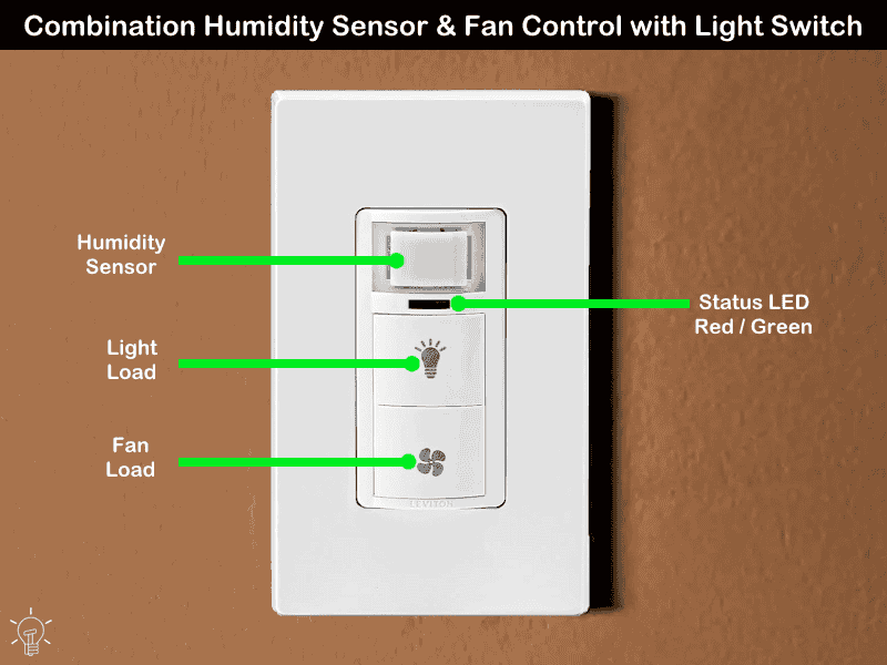
Rating & Features
- Name: Combination Humidity Sensor and Fan Control with Light Switch – Decora DHD05
- Poles: Single-Pole
- Voltage: 120V 1-Phase AC Supply – 60 Hz
- Fan Load: ¼ Motor Fan, 300W LED/CFL, 600W Incandescent/Halogen or 400VA (ELV/MLV)
- Light Load: 150W LED/CFL, 250W Incandescent/Halogen or 200VA (ELV) / 250VA (MLV). 2A resistive load
- Time Delay: 10, 20, 30, and 45 Mins.
- Wire Size: #14 – #12AWG Copper
- Neutral Wire: Preferred, but not needed
- Termination: Wired Leads
Wiring a Combination Humidity Sensor and Fan Control with Light Switch
In this wiring tutorial, we will show how to install a combination humidity sensor and fan controller with a single-pole light switch. Once installed, the controller can be configured for automatic ventilation and air-circulation modes, allowing continuous operation with selectable hourly preset time-out settings.
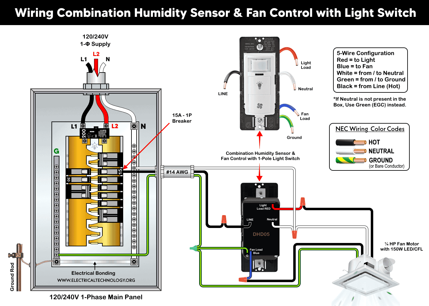
The following wiring diagram illustrates a combination humidity sensor, fan control, and light switch (DHD05) used to control a ceiling, exhaust, or ventilation fan, along with either a built-in light fixture or a separate lighting point. The humidity sensor switch is supplied through a 15A, 120V circuit breaker connected to a 120/240V panelboard.
As shown in the wiring diagram, the combo humidity sensor with 5 built-in wires is connected to the branch-circuit conductors as follows:
- The hot (black) wire from the circuit breaker is connected to the LINE terminal.
- The neutral (white) wire from the panel is connected to the N (Neutral) terminal of the switch and then continued to the load.
- The equipment grounding conductor (bare copper or green wire) from the panel is connected to the G (Ground) terminal.
- The light is connected to the LIGHT LOAD terminal through the switch’s built-in red wire.
- The fan is connected to the FAN LOAD terminal through the switch’s built-in blue wire.
Since the DHD05 humidity sensor switch controls both the fan and the light, both the red and blue wires are used. If only the fan is to be controlled, cap the red wire with a wire connector (wire nut) and leave it safely inside the electrical box as an unused conductor. Alternatively, you may install other humidity sensor models without a built-in light switch, such as the DHS05 or IPHS5.
If the fan and light are on the same line (hot), there is no need to connect the red wire to the light. In this case, the fan switch will control both the fan and the light.
Click image or open in a new tab to enlarge
Testing & Setting
Restore power to the switch and wait 20 seconds for the sensor to properly power up. During this time, the green light on the switch will blink every 5 seconds.
Press both buttons to test the load (fan and light). If everything is working as planned, install the wall plate to mount the in-wall switch.
The device can be set up for 10, 20, 30, or 45 minutes. By default, it is configured for 20 minutes, with Auto-ON high sensitivity and a humidistat set at 50% Relative Humidity (RH), while the bath fan operates in Auto ON/OFF mode.
For programming the setting type and operating mode (such as Test Mode, Bath/Fan Mode, Air Cycle Mode, or Humidity Stat Mode), refer to the step-by-step user manual and follow the instructions provided.
Despite the automatic operation, the exhaust fan can be activated manually by pressing the fan icon on the face of the switch.
Instructions & Precautions.
- Always disconnect the power supply by switching OFF the circuit breaker at the main service panel before performing any electrical work.
- Do not use aluminum wires with this device. Only use copper or copper-clade conductors.
- Do not install the switch directly above a heat source or in locations where hot or cold air drafts can blow directly onto the sensor. Because the motion sensor is sensitive to temperature changes, such conditions may result in false triggering or reduced detection performance.
- Humidity sensor based devices are intended for indoor use only.
- If you are unsure about any part of the installation, consult a licensed electrician and ensure compliance with applicable local electrical codes.
Disclaimer:
- The author will not be liable for any losses, injuries, or damages from the display or use of this information or if you try any circuit in wrong format. So please! Be careful because it’s all about electricity and electricity is too dangerous. If you are unsure, contact a licensed electrician to do it according to the local area codes.
Resources:
Smart Devices Wiring Series
- How to Wire a Smart Switch in a 120/240V Load Center
- How to Wire 120/240V Smart Load Center with Smart Breakers
- How to Wire a Smart Breaker in a Smart 120/240V Panel
- How to Wire a Smart GFCI Breaker in a 120/240V Smart Panel
- How to Wire Smart AFCI/GFCI Breaker in a Smart Load Center
- How to Wire a 15A Wi-Fi Smart Outlet in a Smart Panel
- How to Wire 15A and 20A Wi-Fi Smart GFCI Outlets
- How to Wire Z-Wave Smart Switch, Dimmer & Fan Speed Controller
- How to Wire a Digital and Wi-Fi Smart LED Dimmer Switch
- How to Wire a Smart Switch Companion with a Smart Switch
- Wiring a Smart Dimmer Switch Companion with a Digital Dimmer
- How to Install a Wire-Free Smart Dimmer Anywhere Companion
- How to Wire Smart Scene Controller Switch
- How to Install a Wireless Smart Scene Switch
- How to Install a Wake and Sleep Wireless Smart Switch
- How to Wire a Smart Motion Sensing Dimmer Switch
- How to Wire Humidity Sensor and Fan Control Switch
Wiring Standard GFCI & Breakers
- How to Wire a 1-Pole Breaker
- How to Wire a 2-Pole Breaker
- How to Wire a 3-Pole Breaker
- How to Wire a 1-Pole GFCI
- How to Wire a 2-Pole GFCI
- How to Wire a 3-Phase, 3-Pole GFCI
- How to Wire a Tandem Breaker
- How to Wire GFCI Circuit Breakers
- How to Wire an AFCI Breaker
Wiring General Outlets & GFCI/AFCI Receptacles
- How to Wire an Outlet Receptacle? Socket Outlet Wiring Diagrams
- How to wire a GFCI Outlet?
- How to Wire an AFCI Outlet?
- How to a Wire 3-Way Combination Switch and Grounded Outlet?
- How to Wire a 15A – 125V Outlet – NEMA 5-15 Receptacle
- How to Wire a 20A – 125V Outlet – NEMA 5-20 Receptacle
- How to Wire a 15A – 250V Outlet – NEMA 6-15 Receptacle
- How to Wire a 20A – 250V Outlet – NEMA 6-20 Receptacle
- How to Wire a 50A – 125/250V Outlet – NEMA 14-50 Receptacle
Switches Wiring
- How to Wire Single Pole, Single Throw (SPST) as 2-Way Switch?
- How to Wire Single Pole, Double Throw (SPDT) as 3-Way Switch?
- How to Wire Double Pole, Single Throw Switch? Wiring DPST
- How to Wire Double Pole, Double Throw Switch? Wiring DPDT
- How to Wire Double Switch? 2-Gang, 1-Way Switch – IEC & NEC
- How to Wire 4-Way Switch (NEC) or Intermediate Switch as 3-Way (IEC)?
- How to Wire Auto & Manual Changeover & Transfer Switch – (1 & 3 Phase)
Sizing Breakers, Wires & Panels
- How to Size a Load Center, Panelboards and Distribution Board?
- How to Determine the Right Size Capacity of a Subpanel?
- How to Find the Right Wire Size for 100A Service 120V/240V Panel?
- How to Size a Circuit Breaker?
- How to Find the Proper Size of Wire & Cable In Metric & Imperial Systems
- How to Size a Breaker and Wires in AWG with EGC for Load?
- How to Size Service-Entrance Conductors and Feeder Cables?
- How to Size Feeder Conductors with Overcurrent Protection
- How to Size a Branch Circuit Conductors with Protection?
- How to Size Equipment Grounding Conductor (EGC)?
- How to Size Grounding Electrode Conductor (GEC)?
- How to Size Main Bonding Jumper (MBJ)?
- How to Size Motors FLC, HP, Voltage, Breaker Size and Wire Size
- What is the Correct Wire Size for 100A Breaker and Load?
- What is the Right Wire Size for 15A Breaker and Outlet?
- What is the Suitable Wire Size for 20A Breaker and Outlet?
Finding the Number of Breakers/Outlets in a Circuit
- How to Determine the Number of Circuit Breakers in a Panelboard?
- How to Find the Number of Outlets on a Single Circuit Breaker?
- How to Find Voltage & Ampere Rating of Switch, Plug, Outlet & Receptacle
- How to Calculate the Number of Fluorescent Lamps in a Final Sub Circuit?
- How to Calculate the Number of Incandescent Lamps in a Final Sub Circuit?
- How to Determine the Number of Lighting Branch Circuits?
- How to Determine the Number of Branch Circuits? – 3 Ways
- How to Find the Number of Lights on a Single Circuit Breaker?