How to Wire a Digital & Smart Fan Speed Controller Switch
Wiring a Digital and Smart Ceiling Fan Speed Controller with Neutral Wire in a 120/240V Panel
Smart Fan Speed Controller
The Smart Fan Speed Controller Switch transforms a standard ceiling fan into a smart, connected device for improved comfort and air circulation throughout the home. It provides automatic and manual ON/OFF control and four-speed operation i.e. low, medium, high, or maximum. The controller is ideal for ceiling fans installed in rooms with high or vaulted ceilings where manual adjustment may be difficult. By using the smart celling fan switch, the airflow in the room can be controlled without relying on a pull chain.
The controller device can be configured to create schedules, adjust fan speeds remotely, and set an auto-shutoff timer using smartphone. The ON/OFF operation can be controlled automatically in peak hours which is beneficial in energy savings and reduce electric bill. The device connects directly to a 2.4 GHz Wi-Fi network without requiring a hub and works with popular smart home platforms, i.e. Google Assistant, Amazon Alexa, Apple Siri, Apple Home, SmartThings, and Matter-compatible systems.
The Leviton Decora smart fan speed controller with LED indicator (D24SF) can be customized such as preferred startup speed, return-to-last-speed operation, and minimum/maximum speed limits. It is designed for use with overhead ceiling paddle fans up to 1.5A. For proper operation, it requires a neutral wire connection.
In addition, the smart fan speed control switch can be wired for single load (as single-pole), 3-way, or multi-location applications when used with compatible wired or warless companion devices (such as wired smart dimmer switch companion (DD00R), smart switch companion (DD0SR) or wireless anywhere dimmer companion (DAWDC) or anywhere switch companion (DAWSC). Moreover, it can be paired with the motion-sensing dimmer (D2MSD) to automatically turn the fan on when you enter the room and turn it off when you leave. Hence, it helps to reduce energy consumption.
Rating & Features
- Name: Smart Fan Speed Controller Switch – Decora D24SF
- Poles: Single-Pole, 3-Way & Multiway – With Neutral
- Voltage: 120V 1-Phase AC Supply – 60 Hz
- Current: 1.5A Fan Motor
- Wire Size: #14 – #12AWG Copper
- Bridge / HUB: NO
- Termination: Wired Leads
- Network: Wi-Fi – 802.11 b/g/n networks @ 2.4GHz, Bluetooth – v5.0 with WPA, WPA2, WPA3, or open security
- UL Listed: UL 60730-1 and CAN/CSA-E60730-1
- Compatibility: Amazon Alexa, Google Assistant (Hey Google / Google Home), Apple HomeKit/Siri, SmartThings, Matter, IFTTT, Schlage & My Leviton App (Android/iOS).
Wiring a Smart Fan Speed Controller Switch with Neutral Wire
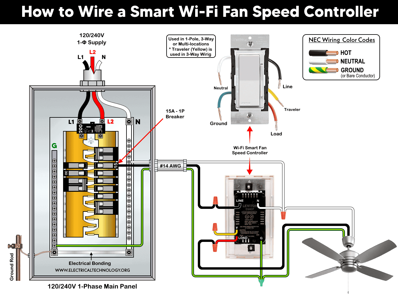
In the following wiring tutorial, we will show how to install the 2nd generation Decora smart fan speed controller (D24SF) and control via an active Wi-Fi network. As shown in the wiring diagram, the smart fan speed controller switch is wired through a 15A, 120V circuit breaker in a 120/240V panel to control the ceiling fan.
Before installing a new switch or replacing an existing single-pole switch, make sure the power is completely disconnected at the circuit breaker or fuse.
As per the wiring diagram, connect the 5-built-in wires in the smart switch to the branch circuit conductors and load as follows:
- Connect the hot (black) wire from the circuit breaker to the LINE terminal.
- Connect the neutral (white) wire from the panel to the N (Neutral) terminal of the switch and then continued to the load (ceiling fan).
- Connect the equipment grounding conductor (bare copper or green wire) from the panel to the G (Ground) terminal.
- Connect the Load (switch’s built-in Red wire) to the the fan.
- The “T” terminal (switch’s built-in Blue wire) is used for three-way/multi-way control. In case of single load, cap the red wire with a wire connector (wire nut) and fix it safely inside the electrical box as an unused conductor.
Click image or open in a new tab to enlarge
Wiring a Digital Fan Speed Control Switch
The Decora digital fan speed control (DDF01) is the older model and can be controlled using Bluetooth® technology. Both fan speed control switches have similar ratings and features, however, the D24SF uses Wi-Fi connectivity, whereas the DDF01 operates via Bluetooth.
The wiring configuration is also the same for both switches. Each model has five built-in wires and provides four-speed fan control with 1.5A rating, as shown in the wiring diagram above. Therefore, there is no need to include a separate wiring diagram for this section.
If you are wondering which one to choose:
- Choose digital fan speed controller (DDF01) if you want a standalone digital fan controller with Bluetooth control and timer functions (i.e. local smartphone control without Wi-Fi).
- Choose smart Wi-Fi fan speed controller (D24SF) if you want smart-home integration, voice control, remote access, scheduling, Matter support, and future expandability.
In short, the D24SF is generally the better choice, as the DDF01 is based on an older Bluetooth platform while the D24SF is controlled through a Wi-Fi network and a part of Leviton’s latest smart-home ecosystem.
Testing, Setting & Adding to the Network
After installation, restore the power and the status LED on the device will blink green. It indicates the device is receiving power and in setup mode. Disconnect the associated breaker in the panel to complete the installation and setup.
Now download My Leviton App for smart devices (compatible with Apple and Android devices). Lunch the app and tap the “+” in the upper right corner. Select “add a device”, and follow the on-screen instructions to add and configure your smart switch. Once set up, you can control your celling fan remotely as well as manually. To add a smart device to the app, follow the simple instruction given in setting My Leviton app with decora smart devices.
The flashing LED indicator table for smart devices shows the different stats of the device during setup and configuration.
To reset the device, press and hold the top rocker for 14 seconds. After the first 7 seconds, the LED will begin flashing Amber. Continue holding for another 7 seconds until the LED flashes Red/Amber. Release the rocker, and the device will be restored to its factory default settings.
Instructions & Precautions.
- Always disconnect the power supply by switching OFF the circuit breaker at the main service panel before performing any electrical work.
- Do not use with fans that have built-in electronic speed controls. Only one fan speed controller may be connected to a single fan load.
- Do not use this device to control exhaust fans, ventilation fans, lighting loads, or ceiling fans with integrated light kits. Refer to the alternatives listed above for these applications.
- Use only with ceiling paddle fans or pull-chain-controlled fans equipped with split-capacitor or shaded-pole motors.
- The wire length between the smart switch and any companion device must not exceed 300 ft (90 m).
- Do not use aluminum wires with this device. Only use copper or copper-clade conductors.
- The minimum recommended wall box depth for installation is 2-3/4 inches (70 mm).
- Installation in a metal wall box or with a metal wall plate may reduce RF signal performance and wireless communication range.
- For 3-way or multi-location applications, do not use standard mechanical switches. Instead, use compatible smart wired or wireless companion switches (mentioned above).
- Smart devices are intended for indoor use only.
- If you are unsure about any part of the installation, consult a licensed electrician and ensure compliance with applicable local electrical code
Disclaimer:
- The author will not be liable for any losses, injuries, or damages from the display or use of this information or if you try any circuit in wrong format. So please! Be careful because it’s all about electricity and electricity is too dangerous. If you are unsure, contact a licensed electrician to do it according to the local area codes.
Resources:
Smart Devices Wiring Series
- How to Wire a Smart Switch in a 120/240V Load Center
- How to Wire 120/240V Smart Load Center with Smart Breakers
- How to Wire a Smart Breaker in a Smart 120/240V Panel
- How to Wire a Smart GFCI Breaker in a 120/240V Smart Panel
- How to Wire Smart AFCI/GFCI Breaker in a Smart Load Center
- How to Wire a 15A Wi-Fi Smart Outlet in a Smart Panel
- How to Wire 15A and 20A Wi-Fi Smart GFCI Outlets
- How to Wire Z-Wave Smart Switch, Dimmer & Fan Speed Controller
- How to Wire a Digital and Wi-Fi Smart LED Dimmer Switch
- How to Wire a Smart Switch Companion with a Smart Switch
- Wiring a Smart Dimmer Switch Companion with a Digital Dimmer
- How to Install a Wire-Free Smart Dimmer Anywhere Companion
- How to Wire Smart Scene Controller Switch
- How to Install a Wireless Smart Scene Switch
- How to Install a Wake and Sleep Wireless Smart Switch
- How to Wire a Smart Motion Sensing Dimmer Switch
- How to Wire a Combo Humidity Sensor & Fan Control with Light Switch
- How to Wire Humidity Sensor and Fan Control Switch
- How to Wire a Countdown Timer Switch – 15 Mins to 12Hrs
Wiring Standard GFCI & Breakers
- How to Wire a 1-Pole Breaker
- How to Wire a 2-Pole Breaker
- How to Wire a 3-Pole Breaker
- How to Wire a 1-Pole GFCI
- How to Wire a 2-Pole GFCI
- How to Wire a 3-Phase, 3-Pole GFCI
- How to Wire a Tandem Breaker
- How to Wire GFCI Circuit Breakers
- How to Wire an AFCI Breaker
Wiring General Outlets & GFCI/AFCI Receptacles
- How to Wire an Outlet Receptacle? Socket Outlet Wiring Diagrams
- How to wire a GFCI Outlet?
- How to Wire an AFCI Outlet?
- How to a Wire 3-Way Combination Switch and Grounded Outlet?
- How to Wire a 15A – 125V Outlet – NEMA 5-15 Receptacle
- How to Wire a 20A – 125V Outlet – NEMA 5-20 Receptacle
- How to Wire a 15A – 250V Outlet – NEMA 6-15 Receptacle
- How to Wire a 20A – 250V Outlet – NEMA 6-20 Receptacle
- How to Wire a 50A – 125/250V Outlet – NEMA 14-50 Receptacle
Switches Wiring
- How to Wire Single Pole, Single Throw (SPST) as 2-Way Switch?
- How to Wire Single Pole, Double Throw (SPDT) as 3-Way Switch?
- How to Wire Double Pole, Single Throw Switch? Wiring DPST
- How to Wire Double Pole, Double Throw Switch? Wiring DPDT
- How to Wire Double Switch? 2-Gang, 1-Way Switch – IEC & NEC
- How to Wire 4-Way Switch (NEC) or Intermediate Switch as 3-Way (IEC)?
- How to Wire Auto & Manual Changeover & Transfer Switch – (1 & 3 Phase)
Sizing Breakers, Wires & Panels
- How to Size a Load Center, Panelboards and Distribution Board?
- How to Determine the Right Size Capacity of a Subpanel?
- How to Find the Right Wire Size for 100A Service 120V/240V Panel?
- How to Size a Circuit Breaker?
- How to Find the Proper Size of Wire & Cable In Metric & Imperial Systems
- How to Size a Breaker and Wires in AWG with EGC for Load?
- How to Size Service-Entrance Conductors and Feeder Cables?
- How to Size Feeder Conductors with Overcurrent Protection
- How to Size a Branch Circuit Conductors with Protection?
- How to Size Equipment Grounding Conductor (EGC)?
- How to Size Grounding Electrode Conductor (GEC)?
- How to Size Main Bonding Jumper (MBJ)?
- How to Size Motors FLC, HP, Voltage, Breaker Size and Wire Size
- What is the Correct Wire Size for 100A Breaker and Load?
- What is the Right Wire Size for 15A Breaker and Outlet?
- What is the Suitable Wire Size for 20A Breaker and Outlet?
Finding the Number of Breakers/Outlets in a Circuit
- How to Determine the Number of Circuit Breakers in a Panelboard?
- How to Find the Number of Outlets on a Single Circuit Breaker?
- How to Find Voltage & Ampere Rating of Switch, Plug, Outlet & Receptacle
- How to Calculate the Number of Fluorescent Lamps in a Final Sub Circuit?
- How to Calculate the Number of Incandescent Lamps in a Final Sub Circuit?
- How to Determine the Number of Lighting Branch Circuits?
- How to Determine the Number of Branch Circuits? – 3 Ways
- How to Find the Number of Lights on a Single Circuit Breaker?