How to Wire a 15A – 125V Outlet – NEMA 5-15 Receptacle
How to Install a Standard 15A – 125V Receptacle (NEMA 5-15) with Breaker and GFCI Protection
A standard 15A, 120V receptacle outlet is a common electrical fixture used in North American homes to power everyday small appliances and lighting that draw less than 15 amps of current. It features two vertical slots and a U-shaped grounding hole.
The slot configuration consists of a wider, longer left slot (neutral), a narrower right slot (hot), and a round or U-shaped hole (ground). This type of outlet is typically installed on circuits protected by a single-pole 120V, 15-amp breaker or GFCI. A #14AWG for 3 wire configuration including the EGC is used to wire a 15A-120V outlet.
The NEMA 5-15 is a 2P, 3W receptacle capable of handling a non-continuous load of up to 15 amps at 125V, providing a maximum power capacity of 1,800 watts on a single-phase circuit. For continuous loads, it can safely handle 12 amps at 120V i.e. 1,440 watts.
In the following wiring tutorial, we will show how to wire a NEMA 5-15 receptacle using both standard and GFCI breakers. The wiring diagrams also illustrate the correct breaker and wire sizes used with a 15-amp receptacle for both continuous and non-continuous load applications.
- Related Post: How to Wire a 15A Wi-Fi Smart Outlet in a Smart Panel
The NEMA 5-15 Outlets and Receptacles
The NEMA 5-15R is a 15A – 125V grounded receptacle designed for use with a NEMA 5-15P plug. As the name suggests, the “15” in 5-15R indicates the maximum current rating in amperes, while the “R” stands for “Receptacle” (outlet). Similarly, the “P” in NEMA 5-15P denotes “Plug,” with “15” indicating its maximum current capacity in amperes.
The 15A, 125V duplex receptacle features a 2-pole, 3-wire configuration. It has two parallel vertical slots i.e. the narrower slot for the hot wire and the wider slot for the neutral. In addition, the round or U-shaped hole is used for the equipment grounding conductor (EGC) pin. This receptacle type is commonly used in the U.S., Canada, and other NEC-compliant countries for powering small appliances such as lamps, ceiling fans, and phone or laptop chargers operating on 125V, 15A circuits.
Click image or open in a new tab to enlarge
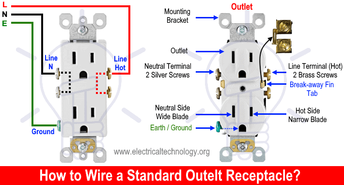
Terminals
There are three terminals in a 5-15R outlet in accordance with UL/CSA.
- U Shaped “G” Terminal – (Green Screw): For equipment grounding conductor (EGC – ⏚) – Bare / Green Wire.
- Narrow / Shorter Terminal (I) on the Right Side – (Brass Screw) – Connects to the Hot Wire – Black Wire
- Longer / Wider Terminal (|) on the Left Side – (Silver Screw): Connects to the Neutral Wire – White Wire
Electrical Ratings & Specifications
- NEMA: 5-15R – Straight-Blade, Duplex Receptacle
- Poles: 2-Poles, 3 Wires Grounding
- Voltage: 125V Single-Phase AC Supply – 60 Hz
- Current: 15A – 12A
- Breaker / GFCI: 15A – 1P
- Wattage: 1,800 W
- Wire Size: #14AWG Copper
- Grade & Material: Residential & Commercial Grade – Composite & Temper-resistant (TR)
- Termination: Quickwire Push-In & Side Wired
- Mounting: Flush / Screw Mounting
- Wiring: Hardwired / Dedicated Circuit
Wiring NEMA 5-15R Outlet
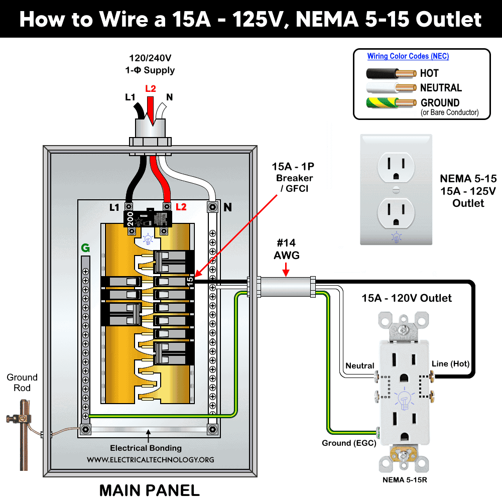
Wiring 15A – 120V Outlet using 1-P Breaker
As shown in the wiring diagram, connect the terminals of the 15A, 125V outlet (NEMA 5-15R) to a single-pole, 15A breaker in a 120/240V main panel as follows:
- Connect the Hot (black) wire to the shorter/narrow slot terminal with the brass screw.
- Connect the Neutral (white) wire to the wider/longer slot terminal with the silver screw.
- Connect the Ground (bare or green) wire to the centered, round/U-shaped “G” terminal with the green screw.
For this configuration, use #14 AWG copper conductors which is suitable size for a 15A circuit and the corresponding NEMA 5-15R outlet.
Click image or open in a new tab to enlarge
During installation, tighten all terminal screws to approximately 14-18 in·lbs (1.6-2 N·m) of torque. Strip the insulation from the conductors according to the connection type:
- Side wire: 3/4″ (19 mm or 1.9 cm)
- Back wire: 1/2″ (12.7 mm or 1.27 cm)
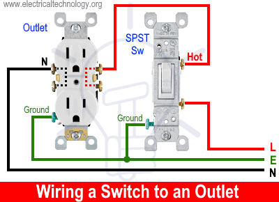
Wiring a 15A – 120V Switched Outlet
Following the same wiring diagram shown above, a 15A–120V outlet can be wired and controlled using a single-pole, single-throw (SPST) 15A switch.
As illustrated in the figure, the hot (black) wire from the single-pole 15A breaker is connected to the line terminal (hot) of the SPST switch. The outgoing hot wire from the switch is then connected to the brass terminal (Hot side) of the outlet. The neutral (white) and ground (bare or green) wires are connected to the outlet in the same way as in ordinary outlet wiring.
This way, the ON/OFF operation of the 15A – 120V outlet can be controlled using a switch. When the switch is ON, the outlet will be energized (operational), and when the switch is OFF, the outlet will be de-energized (off).
If the breakaway fin tab between the brass terminals of the outlet remains intact, both receptacles will be controlled together by the switch for ON/OFF operation. However, if the tab between the hot terminals is removed, only the upper receptacle of the duplex outlet will be controlled by the switch, while the lower receptacle will remain energized regardless of the switch position.
Click image or open in a new tab to enlarge
Keep in mind that the brass screws (hot terminals) in duplex receptacles are electrically connected to each other through a breakaway fin (tab). Therefore, connecting one brass screw to the hot wire will supply power to the second brass screw as well. In some cases, you may remove the breakaway fin tab between the two brass screws (hot terminals) to split the outlet for specific applications. This configuration can be seen in wiring diagrams for various outlet/receptacle installations and applications.
Wiring 15A – 120V Receptacle with GFCI
According to NEC 210.8, GFCI protection is required for receptacles installed in garages, basements, outdoors, laundry areas, and other wet or damp locations. Specifically, NEC 210.8(A)(1) through (A)(11) mandates that all outdoor receptacles must be installed downstream of GFCI protection, in accordance with Articles 426.28 and 427.22.
When installing a 15A, 120V outlet in any location where GFCI protection is required by code, you have two options to achieve compliance:
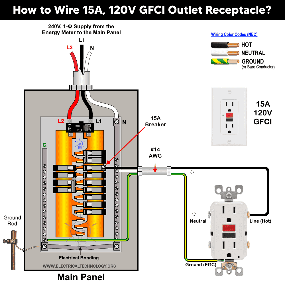
Installing a 15A-120V GFCI Outlet
In this method, the same wiring procedure is followed, but instead of using a standard 15A, 120V receptacle, you will install a 15A, 120V GFCI duplex outlet. The wiring configuration for this setup is shown in the following diagram.
Although this method requires the installation of a GFCI outlet, it helps save space in the main panel since you won’t need to purchase or install a separate GFCI circuit breaker.
Click image or open in a new tab to enlarge
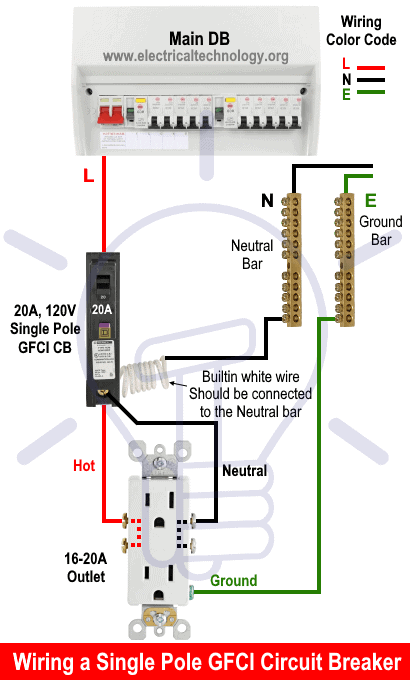
Wiring a 15A-120V Outlet with a GFCI Breaker
If a GFCI outlet is not an option, you can simply remove the standard 15A, 120V breaker and install a GFCI circuit breaker (1-pole, 15A, 120V) instead. The rest of the wiring remains the same as shown in the following wiring diagram.
Click image or open in a new tab to enlarge
FAQs
How Many Amps Can a 15A – 120V Outlet Handle Safely?
A NEMA 5-15 outlet is rated for a maximum non-continuous current of 15 amps at 125 volts AC. For continuous loads (lasting 3 hours or more), the NEC recommends using up to 80% of the outlet rating, which equals 12 amps safely.
How Many Watts Can a 15A – 120V Receptacle Hold?
At 120 volts, a 15-amp outlet can handle up to 1,800 watts (120V × 15A). For continuous use, limit the load to about 1,440 watts (80% of 1,800W).
Which Breaker Size is Suitable for a 15A – 120V Receptacle?
A 1-P, 15-amp circuit breaker is the correct size for a NEMA 5-15 outlet, as per NEC requirements.
What is the Correct Wire Size and Cable Type to Use with a 15A – 120V Outlet?
Based on NEC Table – 310.16, Table – 210.24(1) & NEC 240.4(D)(4), the suitable wire size is 14 AWG copper (or #12 AWG aluminum) to use with a 15A outlet and circuit breaker. Similarly, for protection of a 15A circuit , the equipment grounding conductor (EGC) can be #14 AWG copper, as per NEC Table 250.122.
The most common cable type is 14/2 NM-B (Romex) for indoor wiring, or 14 AWG THHN/THWN in conduit for outdoor or wet locations.
In simple words, According to the National Electrical Code (NEC), a 15-amp circuit should use #14 AWG copper or #12 AWG aluminum (minimum) for safe operation.
Can I Use Smaller Size AWG than 14 AWG with a 15A Outlet?
No. Using smaller wires (like 16 or 18 AWG) is unsafe and violates NEC standards. Always use 14 AWG or larger for 15A circuits. In other words, It is against code to use #16 and #18 AWG wire size for branch circuits because #14 AWG is the smallest branch circuit conductor allowed in the NEC.
Can I Use a 15A Outlet on a 20A Circuit Breaker and Vice Versa?
Yes, you can install a 15A outlet on a 20A circuit breaker, provided the circuit uses 12 AWG wire and the load does not exceed 15A. However, you cannot install a 20A outlet on a 15A circuit breaker, as it could allow devices that draw more current than the circuit can handle.
Can I Use a 20A Outlet on a 15A Circuit and Vice Versa?
- 20A outlet on 15A circuit: Not allowed – it may lead to overloading and violates NEC.
- 15A outlet on 20A circuit: Allowed, as long as the total load doesn’t exceed 15A.
Can a 15A Device be Plugged into a 20A Outlet?
Yes. Most 20A receptacles are designed to accept both 15A and 20A plugs safely. However, a 20A plug can’t be plugged into a 15A receptacle.
Can a 20A Device be Plugged into a 15A Outlet?
No. A 20A plug has a different prong configuration that won’t fit into a 15A outlet, preventing unsafe connections.
Should I Use a GFCI or Standard Breaker for a 15A Outlet?
Use a GFCI outlet or breaker when the receptacle is installed in wet or damp locations (bathroom, kitchen, outdoors, garage, etc.). Otherwise, a standard breaker is acceptable for dry indoor areas.
Can You Install a NEMA 5-15R in a 240V AC Circuit?
No. NEMA 5-15R is designed for 120V only. Operating 120V device on a 240V circuit is dangerous and can damage connected equipment or cause electrical hazards. Alternatively, you may use a NEMA 6-15R for 240V applications.
What is the Recommended Height for Standard Outlet?
The National Electrical Code (NEC) does not specify an exact height for standard (general-purpose) outlets. However, the commonly accepted standard height based on industry practice and local building codes is:
- General wall outlets: 12 to 18 inches (30 to 45 cm) above the finished floor to the center of the receptacle box.
- Outlets above countertops (in kitchens, bathrooms, etc.): Approximately 42 inches (about 107 cm) above the floor, or around 18 inches above the countertop surface.
- Basements, garages, and workshops: Often 4 ft = 48 inches (1.2 m) above the floor for convenience and to keep outlets clear of potential water or obstructions.
Instructions, Precautions & Codes
- A 15A load can be connected to a 20A outlet. It is permissible to use 15A receptacles if there are two or more receptacles (such as duplex) on a 20A circuit.
- It is against the code to connect 20A load on a 15A outlet. In addition, A 20A plug will not fit into a 15A receptacle, and attempting to force it in is dangerous.
- A standard 20-amp outlet accepts both 15-amp and 20-amp plugs (non-T-slot), but not vice versa.
- According to the NEC Table – 310.16 , 210.24.(1) and 240.4(D)(4), the correct Breaker and Wire size for a 15-Amp, 120V (5-15R) outlet is #14 AWG copper or #12 AWG Aluminum.
- Use #14/2 cable (hot wire, a neutral and one ground) for a 15A-120V breaker and receptacle/outlet.
- Longer runs (when the distance is more than 50 ft (15.25 meters) require an upgrade and larger wire gauge size to compensate for voltage drop.
- A 15A outlet can be used for a 12A continuous load and a maximum 15A non-continuous load (210.19(A)), 215.2, and 230.42(A).
- It is against the code to use a 15A outlet to draw 15A on a 10A breaker.
- It is against the code to use smaller gauge wire sizes (e.g., using 16, 18 AWG) instead of 14 AWG wire with a 15A outlet and breaker.
- According to the NEC – 310.16, add 20% of additional ampacity for every 100 feet (30.50 meters) of distance (for example between main panel and subpanel) to counter the voltage drop. For distance and ambient temperature rating (Refer to 110.14(C), 310.15(B)(2)), 310.16 and 240.4(A).
- 15A, 120V outlet can be installed on 15 amp breaker only.
Resources:
Related Wiring Tutorials
Related Wiring Tutorials
NEMA Family Outlets/Receptacle Wiring
NEMA 5 -Series
- How to Wire a 15A – 120V Outlet – NEMA 5-15 Receptacle … (You are Here)
- How to Wire a 20A – 120V Outlet – NEMA 5-20 Receptacle
- How to Wire a 30A – 120V NEMA 5-30 Receptacle
- How to Wire a 50A – 120V – NEMA 5-50 Receptacle
NEMA 6-Series
- How to Wire a 15A – 240V Outlet – NEMA 6-15 Receptacle
- How to Wire a 20A – 240V Outlet – NEMA 6-20 Receptacle
- How to Wire a 30A – 240V – NEMA 6-30 Receptacle
- How to Wire a 50A – 240V – NEMA 6-50 Receptacle
NEMA 10-Series
- How to Wire a 20A, NEMA 10-20 Non-Grounding Receptacle
- How to Wire a 30A, NEMA 10-30 Non-Grounding Receptacle
- How to Wire a 50A, NEMA 10-50 Non-Grounding Receptacle
NEMA 14-Series
- How to Wire a 20A – 125/250V NEMA 14-20 Receptacle
- How to Wire a 30A – 125/250V NEMA 14-30 Receptacle
- How to Wire a 50A – 125/250V NEMA 14-50 Receptacle
- How to Wire a 60A – 125/250V – NEMA 14-60 Receptacle
NEMA General Outlets/Receptacle
- How to Wire a 15A/125V, NEMA 1-15 Non-Grounding Outlet
- How to Wire a 20A/250V, NEMA 2-20 Non-Grounding Receptacle
- How to Wire a 30A – 125V, NEMA TT-30 Receptacle for RVs
- How to Wire a 3-Phase, 60A – 250V NEMA 15-60 Receptacle
- How to Wire a 3-Phase, 60A – 120/208V NEMA 18-60 Receptacle
Smart Devices Wiring Series
- How to Wire 120/240V Smart Load Center with Smart Breakers
- How to Wire a Smart Breaker in a Smart 120/240V Panel
- How to Wire a Smart GFCI Breaker in a 120/240V Smart Panel
- How to Wire Smart AFCI/GFCI Breaker in a Smart Load Center
- How to Wire a Smart Switch in a 120/240V Load Center
- How to Wire a 15A Wi-Fi Smart Outlet in a Smart Panel
- How to Wire 15A and 20A Wi-Fi Smart GFCI Outlets
General Wiring Installations:
- How to Size a Breaker and Wires in AWG with EGC for Load?
- How to Wire an Outlet Receptacle? Socket Outlet Wiring Diagrams
- How to a Wire 3-Way Combination Switch and Grounded Outlet?
- How to Wire Combo Switch and Outlet? – Switch/Outlet Combo Wiring Diagrams
- How to Wire 120V & 240V Main Panel? Breaker Box Installation
- How to Wire a Subpanel? Main Lug Installation for 120V/240V
- How to Wire 277V & 480V, 1-Phase & 3-Phase, Commercial Main Service Panel?
- How to Wire 240V Water Heater Thermostat – Non-Continuous?
- How to Wire 3-Phase Simultaneous Water Heater Thermostat?
- How to Wire Twin Timer for 120V/240V Circuits – ON/OFF Delay
- How to Wire ST01 Timer with Relay & Contactor for 120V/240V Motors?
- How to Wire Multifunction ON/OFF Delay Timer for 120V/240V Motors?
Switches Wiring
- How to Wire Single Pole, Single Throw (SPST) as 2-Way Switch?
- How to Wire Single Pole, Double Throw (SPDT) as 3-Way Switch?
- How to Wire Double Pole, Single Throw Switch? Wiring DPST
- How to Wire Double Pole, Double Throw Switch? Wiring DPDT
- How to Wire Double Switch? 2-Gang, 1-Way Switch – IEC & NEC
- How to Wire 4-Way Switch (NEC) or Intermediate Switch as 3-Way (IEC)?
GFCI/AFCI Breaker/Outlet Wiring
- How to Wire a GFCI Circuit Breaker?
- How to wire a GFCI Outlet?
- How to Wire GFCI Combo Switch and Outlet – GFCI Switch/Outlet
- How to Wire an AFCI Breaker?
- How to Wire an AFCI Outlet?
Related Posts:
- What is the Right Wire Size for 15A Breaker and Outlet?
- What is the Difference Between 15-Amp and 20-Amp Outlet?
- Difference Between Socket, Outlet and Receptacle
- Difference Between NEMA 14-50 Standard Vs EV Receptacle
- Should GFCI Protection Be in the Main Panel or Receptacle?
- Difference Between 1-Pole and 2-Pole Breakers – NEC & IEC
- How to Find the Number of Outlets on a Single Circuit Breaker?
- How to Find Voltage & Ampere Rating of Switch, Plug, Outlet & Receptacle
- Can you use 15A Breaker on 20A Circuit and Vice Versa?
- Can You use a 15A Outlet on a 20A Circuit and Vice Versa?
- Ground Terminal Up or Down: Which Way Should Outlets Face?
- What Do the Green Dot or Orange Triangle Outlets Mean?
- What Do the Different Colors of Electrical Outlets Indicate?
- Why are Outlets and Receptacles in Hospitals Upside Down?
- How to Size a Load Center, Panelboards and Distribution Board?
- How to Determine the Number of Circuit Breakers in a Panelboard?
- How to Find the Proper Size of Circuit Breaker? Breaker Size Calculator & Examples
- How to Find The Suitable Size of Cable & Wire for Electrical Wiring Installation?
- Why is the Neutral Prong or Slot Wider on a Plug or Outlet?
- What Will Happen If You Connect a Male-to-Male Plug Between Outlets


