How to a Wire Double 3-Way Combination Switch Device?
Installation of Double Three-Way Switch Combo Device for Common & Separated Feed
What is a Double 3-Way Combo Switch Device?
A Three-Way combo switch device is actually the combination of two 3-way switches in a single unit (such as Leviton 5243, 5640, 5643 etc.) It can be used for 120V and 240V circuits where a load point (e.g. light bulb) needs to be controlled from two different places with the help of an additional ordinary 3-way switch. Moreover, It can be used as double switch for ON/OFF switch for lighting circuits.
Related Posts:
- How to a Wire 3-Way Combination Switch and Grounded Outlet?
- How to Wire Double Switch? 2-Gang, 1-Way Switch – IEC & NEC
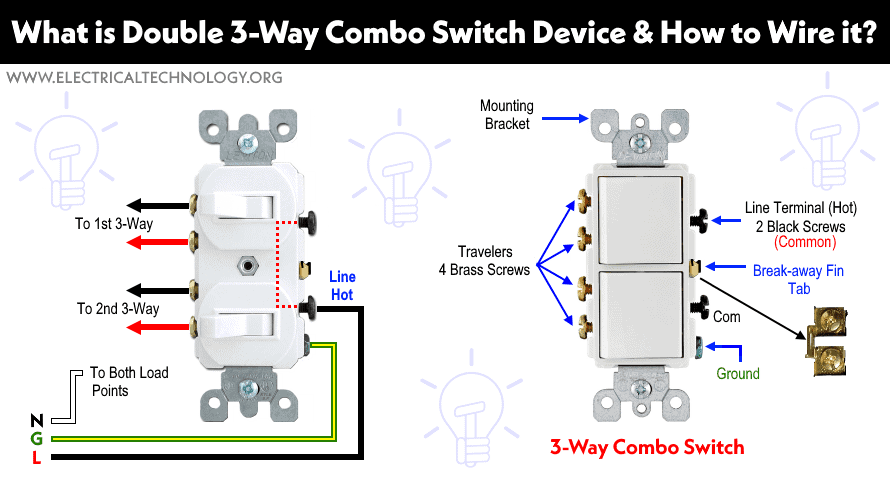
Construction of Double 3-Way Combo Device
The following figure shows the basic construction of a double 3-Way combination switch. It has a total of 7 terminal screws. The four brass screws are for travelers wires while the two black screws are common (hot) which is bonded together by a break-off fin. The break-away fin can be removed to use two separate incoming sources from two different breakers. The green colored screw is used for Grounding wire. Since switches are wired on Hot conductors, there is no need of a silver screw for Neutral wire.
Click image to enlarge
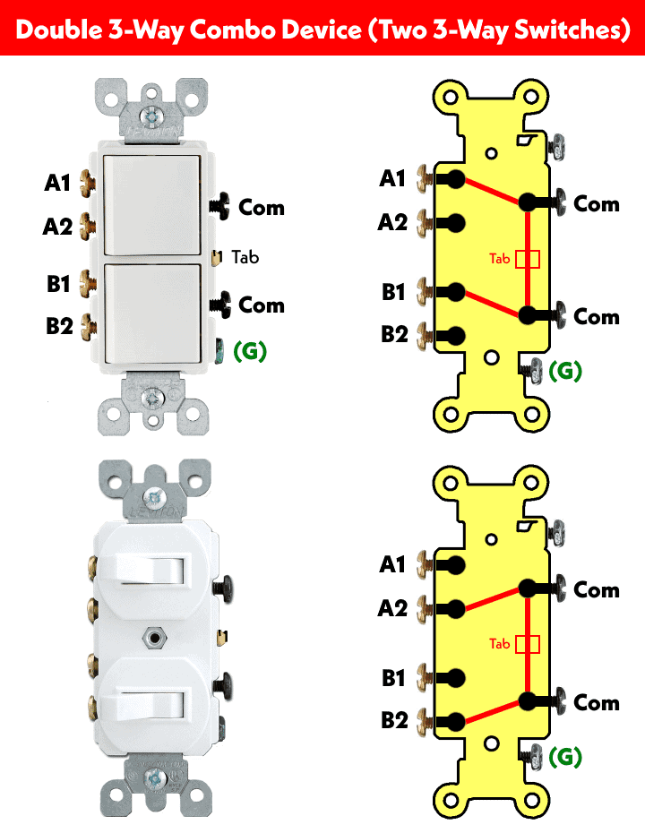
The following figures show the operation of internal contacts in a double three-way combo switch device (combination of a 3-way switches).
Related Posts:
- How to Wire Combo Switch and Outlet? – Switch/Outlet Combo Wiring Diagrams
- How to Wire an Outlet Receptacle? Socket Outlet Wiring Diagrams
Let’s see how to wire these types of switches for different load circuits and applications.
Wiring Double 3-Way Combo Switch Device as Ordinary Double Pole Switch
The following wiring shows a double three-way switch is used as double switch to control two different bulbs for single operation (like two way switch) . To do this, just connect the common of the double 3-way switch (any one of the dark screws on the right) to the Hot wire. Now connect the upper brass screw (number 1) and lower brass screw (number 3) to two different light bulbs. Connect the ground and neutral wires to the bulbs as well.
Click image to enlarge
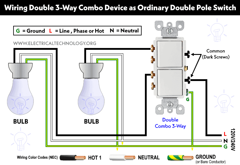
This way, the double 3-way switch can be operated like a double switch for ON and OFF operation same as single pole SPST switch.
Related Posts:
- How to Wire Combo Switch and Outlet? – Switch/Outlet Combo Wiring Diagrams
- How to Wire an AFCI Combo Switch – AFCI Switch Wiring Diagrams
- How to Wire GFCI Combo Switch and Outlet – GFCI Switch/Outlet Wiring Diagrams
Controlling Two Bulbs From Different Places using Double 3-Way Switches
The following wiring diagram shows that two numbers of bulbs are wired and controlled from two different places using two double 2-way switches. As shown, the hot from the breaker is connected to the common (dark screw) of the first double 3-way switch). The A1, A2, B1 and B2 terminals (brass screws) of both double 3-way switches are connected through travelers wires.
The break-away fin of the second double 3-way switch has been removed and the upper and lower dark screws are connected to two separate bulbs. Finally, Neutral and earth are wired to the light bulbs. This way, both bulbs can be controlled from two different locations using double 3-way switches.
Click image to enlarge
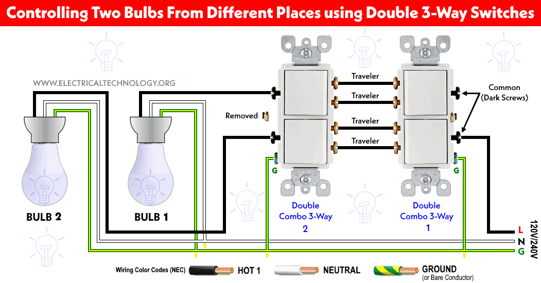
Keep in mind that you can control a single light bulb using the above wiring e.g. you may only connect the upper dark screw to a light bulb where the lower dark screw of the second double 3-way switch and its terminals of B1 and B2 are unused.
Related Posts:
- How to Wire Combo Switch and Outlet? – Switch/Outlet Combo Wiring Diagrams
- How to Wire an Outlet Receptacle? Socket Outlet Wiring Diagrams
Wiring Double Combination Switch Device with Two Ordinary 3-Way Switches using Common Feed
The following wiring diagram shows how to control two light bulbs from two different places using a double 3-way combination switch and two numbers of ordinary 3-way switches using common feed. It clearly shows that the incoming Hot (Line) wire is connected to the common dark screws of combo switch that are bonded together via break-off tab.
Click image to enlarge
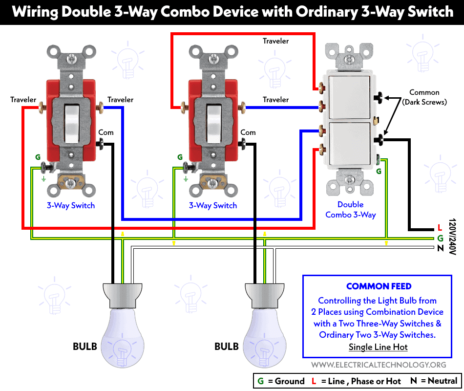
The upper two brass terminals of the double 3-way combo device are wired to the A1 and A2 terminals of a 1st typical 3-way switch via travelers wires. Similarly, the lower two brass terminals of three-way combo switch are wired to the second ordinary 3-way switch via travelers wires. The common terminals of both ordinary 3-way switches are connected to two light bulbs as shown below.
The ground wires are connected to all three switches and a light bulbs. This way, both light bulbs can be controlled for ON and OFF operations from two different locations.
Related Posts:
- How to Find the Number of Outlets on a Single Circuit Breaker?
- How to Find Voltage & Ampere Rating of Switch, Plug, Outlet & Receptacle
Wiring Double 3-Way Combo Switch Device with Ordinary 3-Way Switches using Separate Feed
The following wiring diagram shows how to control a bulb from two different locations using a double 3-way combo device and typical 3-way switches using separate feed (2 Hot lines).
The wiring diagram is the same as above except the break-away tab is removed from the common terminal side of the double 3-way combo device. Hence, one screw is connected to Hot 1 (120V from a breaker) and the second dark screw is connected to Hot 2 (120V from another breaker) from the 120/240V main panel. The rest is same as above.
Click image to enlarge
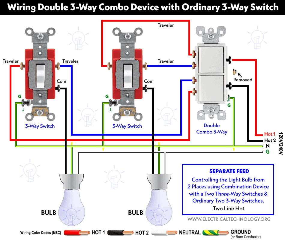
This way, fist light bulb is controlled via (HOT 1) source while the second light bulb is controlled via (Hot 2) source where both circuits can be ON and OFF from 2 different locations. The rest of the circuit and its operation is the same as above.
Related Posts:
- How to Control a Lamp by a Single Way or One-Way Switch?
- How to control each lamp by separately switch in parallel lighting circuit?
Precautions:
Related Posts:
- How To Wire Switches in Series?
- How To Wire Switches in Parallel?
- How To wire Lamps in Series?
- How To Wire Lamps in Parallel?
- How to Control a Lamp by a Single Way or One-Way Switch?
- How to control each lamp by separately switch in parallel lighting circuit?
- How to Wire Single Pole, Double Throw (SPDT) Switch? IEC & NEC
- How to Wire Double Pole, Double Throw (DPDT) Switch? IEC & NEC
- How to Wire 4-Way Switch (NEC) & Intermediate Switch as 3-Way (IEC)?
- How to Wire Single Pole, Single Throw (SPST) Switch? IEC & NEC
- How to Wire Single Pole, Double Throw (SPDT) Switch? IEC & NEC
- How to Wire a Pilot Light Switch? Wiring of 2 & 3 Way Neon Light Switches
- How to Control Water Heater using Switches?
- How to Wire a Ceiling Fan? Dimmer Switch and Remote Control Wiring
- How to Wire Auto & Manual Changeover & Transfer Switch – (1 & 3 Phase)
- Automatic Bathroom Light Switch Circuit Diagram and Operation
- Staircase Wiring Circuit Diagram – How to Control a Lamp from 2 Places by 2-Way Switches?
- 2 Way Switch – How to Control One Lamp From Two or Three Places?
- How to Control One Light Bulb from Six Different Places using 2-Way & Intermediate Switches?
- Corridor Wiring Circuit Diagram – Hallway Wiring using 2-Way Switches
- Hospital Wiring Circuit for Light Control using Switches
- Tunnel Wiring Circuit Diagram for Light Control using Switches
- Godown Wiring Diagram -Tunnel Wiring Circuit and Working
- Hostel Wiring Circuit Diagram and Working
- How to Wire a UK 3-Pin Plug? Wiring a BS1363 Plug
- How to Wire a UK 3-Pin Socket Outlet? Wiring a BS1363 Socket
- How to Wire a Twin 3-Pin Socket Outlet? Wiring 2-Gang Socket
- Switch and Push Button Symbols
- Basic Electrical Wiring Diagrams


On “double-3-way-combo-switch-device.html” the last diagram for “Wiring Double 3-Way Combo Switch Device with Ordinary 3-Way Switches using Separate Feed” shows the green wire as Neutral and the white wire as Ground!!!! (I can’t believe nobody pointed this out to you before!)
Thank you, Phil, for pointing out the labeling with such an eagle eye. We have made the necessary corrections accordingly.