How to Wire a Smart GFCI Breaker in a 120/240V Smart Panel
How to Wire 1-Pole & 2-Pole Smart GFCI Breakers in a 120/240V Smart Load Center
Smart GFCI Circuit Breakers
Similar to a smart circuit breaker, smart GFCI breakers and dual-function AFCI/GFCI breakers are used in both conventional and smart load centers for home automation systems. These breakers can be monitored and controlled remotely through a smartphone app and can send notifications whenever the breaker trips or is reset.
A GFCI (Ground-Fault Circuit Interrupter) monitors the current balance between the ungrounded (hot) conductor and the grounded (neutral) conductor. If it detects a current imbalance as small as 5mA (indicating leakage to ground), it interrupts the circuit in less than one-tenth of a second. This rapid response helps prevent severe electric shock and reduces the risk of electrical fires by disconnecting power as soon as unintended current flow is detected.
Smart GFCI breakers are available from manufacturers such as Leviton and Eaton. In this wiring guide, we will demonstrate how to install and wire both 1-P and 2-P smart GFCI breakers in standard and smart 120/240V load centers.
The NEC – 210.8(A) requires GFCI protection in areas of the home where moisture or grounding risks are present, such as kitchens, bathrooms, laundry rooms, workshops, basements, garages, and outdoor spaces such as pools.
Rating & Features of a Smart GFCI Breakers
- Name: 2nd Gen Smart GFCI Branch Circuit Breaker with Remote Control
- Poles: 1-Pole & 2-Poles – 2 & 3 Wires with Ground
- Voltage: 120V, 120/208V & 120/240V – Single-Phase AC Supply – 60 Hz
- Current: 15A to 60A
- Short Circuit Current Rating: 10kA
- Wiring: Plug-On
- Control = Manual & Remote ON/OFF & Scheduling
- LED Indicator = Status indication even when breaker is off
- Compatibility: My Leviton App (To be used with Leviton Smart panel and requires the LWHEM-2 or LData Hub)
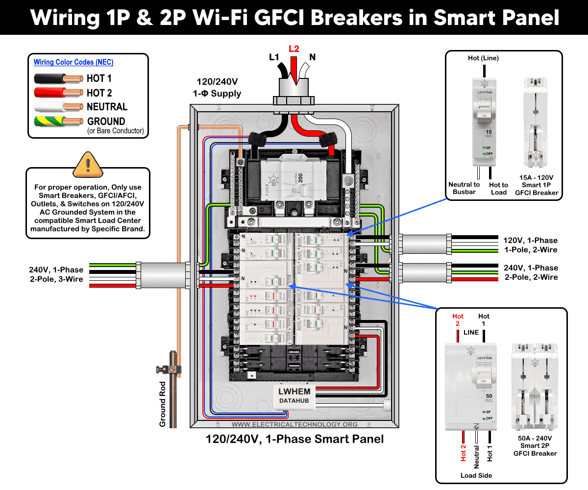
Wiring 1P & 2P Smart GFCI Breakers in a Smart Panel
The following wiring diagram shows a 1-pole 15A/120V (LB115-GS) and 20A – 240V (LB220-GST) and 50A, 2-pole 120/240V (LB250-GST) smart GFCI breakers in a smart 120V/240V load center by Leviton (LP220-BPD).
As shown in the fig, the smart breakers have the following wiring configuration
- 15A/120V – 1 Pole, 2-Wires, 1-Phase
- 20A/240V – 2 Pole, 2-Wires, 1-Phase
- 50A – 120/240V – 2 Pole, 3-Wires, 1-Phase
To wire a smart GFCI breaker in the panel, select the proper size of breaker and follow the following simple steps.
Turn OFF all power to the panel at the main breaker or upstream disconnect. Confirm power is OFF using a tester. Now, remove the cover and snap the plug-on breaker in the panel (hot and neutral) slots.
The following wiring diagram shows the 1P & 2P smart GFCI breakers for 2 wires & 3-wires 120/240V branch circuits
Click image or open in a new tab to enlarge
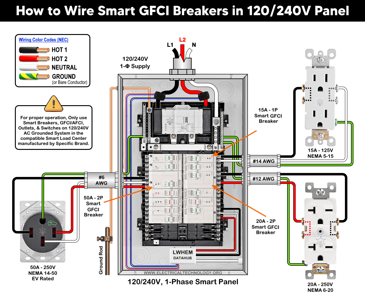
Wiring 1-Pole Smart GFCI Breaker – 120V – 2-Wires
As shown in the wiring diagram, a 1-pole 15A/120V smart GFCI breaker (the first breaker at the top left on the right side of the panel) is wired using #14 AWG conductors. It protects an ordinary 15A/125V outlet (NEMA 5-15 receptacle).
As it is a smart panel and breaker, the neutral conductor supplying the receptacle must be connected to the breaker’s neutral terminal, not to the neutral busbar in the main panel. This configuration allows the GFCI breaker to properly monitor both the hot and neutral conductors for ground-fault protection.
Wiring 2-Pole Smart GFCI Breaker – 240V – 2-Wires
Similarly, a 2-pole 20A smart GFCI breaker (third breaker from the top on the right side) is wired using #12 AWG conductors. It protects a 20A/250V outlet (NEMA 6-20 receptacle).
Because this 240V receptacle does not require a neutral conductor, the breaker’s neutral terminals (silver screws) remain unused.
Wiring 2-Pole Smart GFCI Breaker – 240V – 3-Wires
In addition, a 2-pole 50A 120/240V smart GFCI breaker (third breaker from the top on the left side) is wired to protect an EV rated 50A 125/250V receptacle (NEMA 14-50), especially used for EV charging.
Since this is a 120/240V three-wire circuit (two hot conductors and one neutral), a neutral connection is required. The neutral conductor must be connected to the breaker’s designated neutral terminal (marked “N”), not to the panel’s neutral busbar.
The wiring is little bit difference than the conventional GFCI breakers that use a factory-installed pigtail connected to the neutral busbar, this smart GFCI breaker requires the branch-circuit neutral to terminate directly at the breaker to ensure proper ground-fault sensing.
The following wiring diagram illustrates 1P and 2P smart GFCI breakers for NEMA 15A – 120V, 20A – 250V and 50A – 120/240V outlets and receptacles.
Click image or open in a new tab to enlarge
Finally, use the My Leviton App and the Getting Started Guide to add and enable the GFCI breaker’s smart functions.
Wiring a Smart GFCI Breakers in a Conventional Panel
In the absence of a smart panel, a smart GFCI breaker can still be installed in a conventional load center. For example, Eaton offers a plug-on Wi-Fi breaker with integrated GFCI protection (SBR260WGF – AbleEdge BR smart breaker). This breaker allows smart functionality without requiring a panel upgrade.
The wiring diagram shows a 2-pole smart breaker with GFCI protection installed to protect a 60A, 125/250V receptacle (NEMA 14-60) in a standard 120/240V load center.
Click image or open in a new tab to enlarge
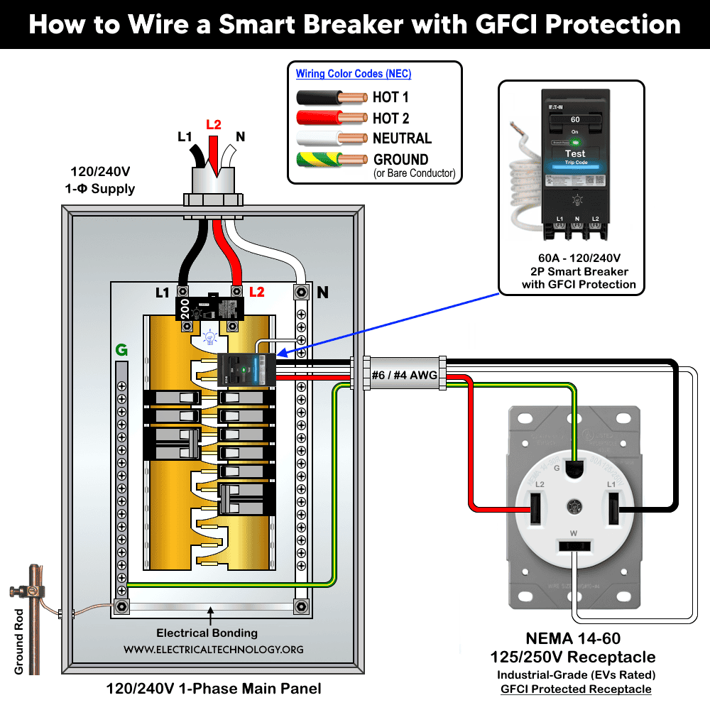
Wiring Method
The wiring method is similar to that of wiring a standard 2-pole GFCI breaker:
- Mount the breaker onto the panel’s main busbars.
- Connect the breaker’s built-in white pigtail to the neutral busbar in the main panel.
- Connect the load conductors from the breaker to the receptacle using #6 AWG or #4 AWG conductors (as required by ampacity and code compliance), as follows:
- Hot 1 – Black
- Hot 2 – Red
- Neutral – White
- Equipment Ground – Bare copper or Green
This configuration ensures proper GFCI operation while enabling smart monitoring and control features through the breaker’s integrated Wi-Fi capability.
To control the smart breaker from anywhere through a Wi-Fi network, download the Eaton Brightlayer Home app (available for iOS and Android on the Google Play Store) and connect the Eaton smart breaker to the app by following the step-by-step setup guide.
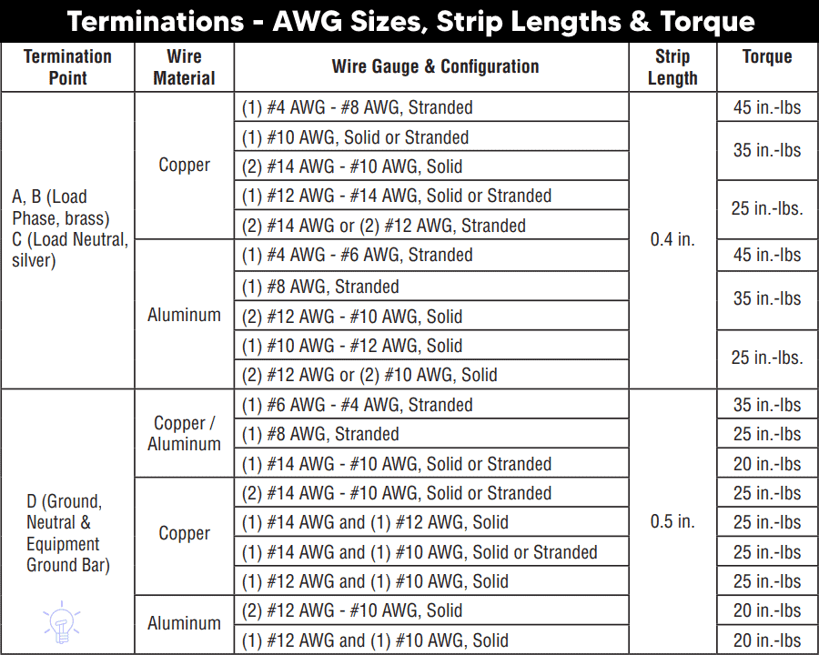
Termination Values:
The wire gauge sizes, insulation strip lengths, and terminal torque specifications listed below apply to common Leviton devices installed in the main electrical panel.
Troubleshooting via LED Status Indictor
The following table shows the troubleshooting and diagnostic of smart GFCI breakers by Leviton using the built-in LED status indicator on it.
| Smart GFCI Breaker LED Status Indicator | |||
| Breaker Handel | GF LED | ON/OFF LED | Device Status |
| Green | OFF | OFF | ON |
| Green | OFF | ON – Solid | Remote OFF |
| Red | OFF | OFF | Short-circuit / Overload Trip |
| Red | ON – Solid | OFF | Ground Fault Trip |
| Red | ON – Blinking | OFF | 0.1 Sec Delay – Replace Breaker |
| Red | ON – Blinking | OFF | 3 sec Delay – Neutral Miswired |
| White | OFF | OFF | Manual OFF |
Precaution:
- Always disconnect the power supply by switching OFF the main breaker before performing any electrical work.
- Never install AFCI, GFCI, AFCI/GFCI or GFPE breakers on circuits with shared neutrals, false or unwanted trips will occur.
- Do not use AFCI/GFCI branch circuit breakers for life-support equipment in hospitals and health services units because the nuisance tripping of the device will cut power to the equipment.
- GFCI and AFCI must be installed using copper / copper-clade conductors only.
- If you are unsure about any step, consult a licensed electrician to ensure the installation complies with applicable local electrical codes and regulations.
- Exercise extreme caution when working with electricity. Improper handling can result in serious injury, property damage, or death.
- If you are unsure about any step, consult a licensed electrician to ensure the installation complies with applicable local electrical codes and regulations.
- The author assumes no liability for any loss, injury, or damage resulting from the use or misinterpretation of this information, or from improper installation of any circuit.
Resources:
Smart Devices Wiring Series
- How to Wire 120/240V Smart Load Center with Smart Breakers
- How to Wire a Smart Breaker in a Smart 120/240V Panel
Main Panels Wiring Tutorials
- How to Wire 120/240V Main Panel – Breaker Box Installation
- How to Wire 120V/208V, 1-Phase & 3-Phase Main Panel?
- How to Wire 120/208/240V High Leg Delta 1-Phase & 3-Phase Main Panel?
- How to Wire 277/480V, 1-Phase & 3-Phase Main Service Panel?
- How to Wire 347/600V, 1 and 3-Phase Main Service Panel?
- How to Wire a Subpanel? Main Lug Installation for 120V/240V
- How to Wire a Spa Panel Box for a Hot Tub using 2P GFCI & Breaker
- Single Phase Electrical Wiring Installation in Home – NEC & IEC
- Three Phase Electrical Wiring Installation in Home – NEC & IEC
- How To Wire a Single Phase kWh Meter – 120V/240V
- How to Wire a Three-Phase Meter? 120/208/240/277/347/480/600V
Wiring Smart / Standard GFCI & Breakers
- How to Wire a 1-Pole Breaker
- How to Wire a 2-Pole Breaker
- How to Wire a 3-Pole Breaker
- How to Wire a 1-Pole GFCI
- How to Wire a 2-Pole GFCI
- How to Wire a 3-Phase, 3-Pole GFCI
- How to Wire a Tandem Breaker
- How to Wire GFCI Circuit Breakers
- How to Wire an AFCI Breaker
Wiring Smart / General Outlets & GFCI/AFCI Receptacles
- How to Wire an Outlet Receptacle? Socket Outlet Wiring Diagrams
- How to wire a GFCI Outlet?
- How to a Wire 3-Way Combination Switch and Grounded Outlet?
- How to Wire a 15A – 125V Outlet – NEMA 5-15 Receptacle
- How to Wire a 20A – 125V Outlet – NEMA 5-20 Receptacle
- How to Wire a 15A – 250V Outlet – NEMA 6-15 Receptacle
- How to Wire a 20A – 250V Outlet – NEMA 6-20 Receptacle
- How to Wire a 50A – 125/250V Outlet – NEMA 14-50 Receptacle
Switches Wiring
- How to Wire Single Pole, Single Throw (SPST) as 2-Way Switch?
- How to Wire Single Pole, Double Throw (SPDT) as 3-Way Switch?
- How to Wire Double Pole, Single Throw Switch? Wiring DPST
- How to Wire Double Pole, Double Throw Switch? Wiring DPDT
- How to Wire Double Switch? 2-Gang, 1-Way Switch – IEC & NEC
- How to Wire 4-Way Switch (NEC) or Intermediate Switch as 3-Way (IEC)?
- How to Wire Auto & Manual Changeover & Transfer Switch – (1 & 3 Phase)
Sizing Breakers, Wires, and Panels
- How to Size a Load Center, Panelboards and Distribution Board?
- How to Determine the Right Size Capacity of a Subpanel?
- How to Find the Right Wire Size for 100A Service 120V/240V Panel?
- How to Size a Circuit Breaker?
- How to Find the Proper Size of Wire & Cable In Metric & Imperial Systems
- How to Size a Breaker and Wires in AWG with EGC for Load?
- How to Size Service-Entrance Conductors and Feeder Cables?
- How to Size Feeder Conductors with Overcurrent Protection
- How to Size a Branch Circuit Conductors with Protection?
- How to Size Equipment Grounding Conductor (EGC)?
- How to Size Grounding Electrode Conductor (GEC)?
- How to Size Main Bonding Jumper (MBJ)?
- How to Size Motors FLC, HP, Voltage, Breaker Size and Wire Size
- What is the Correct Wire Size for 100A Breaker and Load?
- What is the Right Wire Size for 15A Breaker and Outlet?
- What is the Suitable Wire Size for 20A Breaker and Outlet?
Finding the Number of Breakers/Outlets in a Circuit
- How to Determine the Number of Circuit Breakers in a Panelboard?
- How to Find the Number of Outlets on a Single Circuit Breaker?
- How to Find Voltage & Ampere Rating of Switch, Plug, Outlet & Receptacle
- How to Calculate the Number of Fluorescent Lamps in a Final Sub Circuit?
- How to Calculate the Number of Incandescent Lamps in a Final Sub Circuit?
- How to Determine the Number of Lighting Branch Circuits?
- How to Determine the Number of Branch Circuits? – 3 Ways
- How to Find the Number of Lights on a Single Circuit Breaker?
General Wiring Installation Tutorials:
- How to Toggle Electric Water Heater Between 120V and 240V?
- How to Wire 120V Water Heater Thermostat – Non-Simultaneous?
- How to Wire 240V Water Heater Thermostat – Non-Continuous?
- How to Wire 3-Phase Simultaneous Water Heater Thermostat?
- How to Wire Twin Timer for 120V/240V Circuits – ON/OFF Delay
- How to Wire ST01 Timer with Relay & Contactor for 120V/240V Motors?
- How to Wire Multifunction ON/OFF Delay Timer for 120V/240V Motors?
- Even More Residential Wiring Installation Tutorials