How to Wire a 15A Wi-Fi Smart Outlet in a Smart Panel
How to Wire a Smart Outlet – Wiring a 15A Wi-Fi Receptacle in Smart and Standard 120/240V Panels
What is a Smart Outlet?
Smart Wi-Fi outlets provide a practical entry point into residential automation, enabling remote load control, scheduling, energy monitoring, and integration with common smart-home ecosystems. These devices transform an ordinary home into a smarter, more convenient living space. They allow you to control the ON/OFF operation of connected devices from anywhere using a mobile app or a simple voice command through a compatible voice assistant.
Smart devices (outlets, switches, dimmers) from manufacturers such as Leviton and Legrand are designed to retrofit into standard single-gang electrical boxes, which makes them a direct functional replacement for conventional duplex receptacles in branch circuits for residential applications.
One of the key advantages of these smart receptacles is installation compatibility and support for switched outlet to control from anywhere using switch companion devices. In addition, no hub is required for wireless operation. In most cases, they can replace ordinary receptacles without structural modification to the wall box, if:
- The electrical box has sufficient cubic-inch capacity for the additional conductor volume.
- A neutral conductor is present (required for most smart outlets).
- The circuit amperage rating matches the device rating (e.g., 15A or 20A).
If desired, the smart outlet can later be replaced again with a standard, non-smart receptacle using the same wiring configuration, allowing flexibility for future changes or system simplification.
In the following wiring guide, we will show the proper method for removing an existing standard receptacle and installing a compatible smart Wi-Fi outlet. The procedure follows conventional residential wiring practices for 120V circuits in a 120/240V smart panel or standard panel. The given wiring diagrams illustrates the conductor identification, termination methods and app setting for remote control of the load devices.
Rating & Features of a Smart Outlet
- Name: Smart Wi-Fi Outlet – NEMA 5-15
- Poles: 2-Poles, 3 Wires Grounding
- Voltage: 125V Single-Phase AC Supply – 60 Hz
- Current: 5A LED/CFL – 15A Magnetic Load
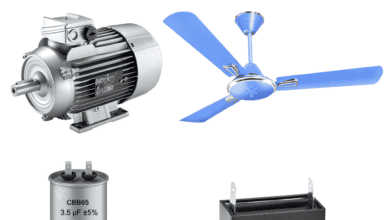
- Wattage: 1500W Incandescent/Halogen Lamps or ¾ HP Motor
- Wire Size: #14AWG Copper
- Termination: Quickwire Push-In, Side Wired – Screw Termination and Mounting
- Compatibility: Amazon Alexa, Google Assistant (Hey Google / Google Home), Apple HomeKit/Siri, SmartThings and Sonos.
Wiring a 15A Wi-Fi Smart Outlet in a Smart Panel
As shown in the wiring diagram, a 15A, 120V smart outlet (such as Decora D215R and ZW15R by Leviton) is supplied through a 15A, single-pole (1P) Wi-Fi smart breaker installed in a smart 120V/240V panel.
Click image or open in a new tab to enlarge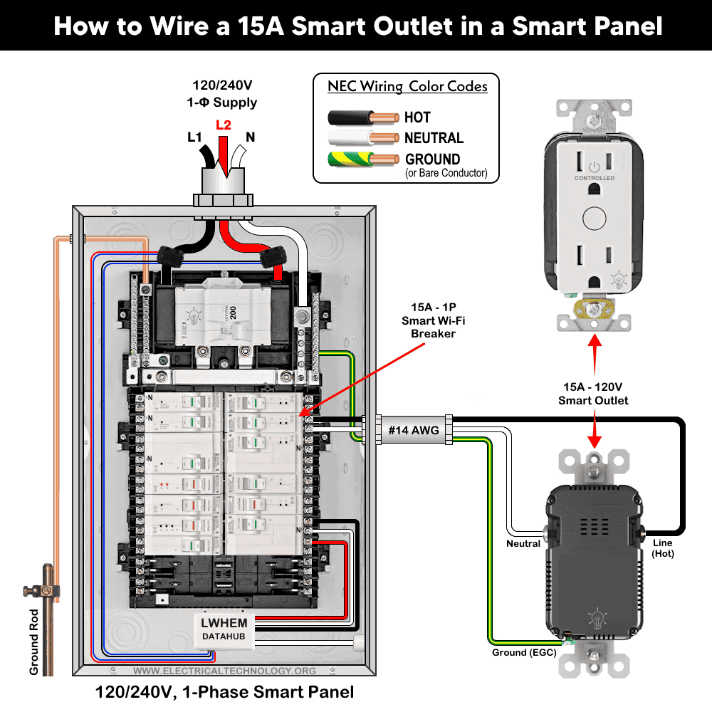
When installing a new smart outlet or replacing an existing standard receptacle, connect the branch circuit conductors from the 15A breaker in the main panel following the given simple steps.
Step 1: Confirm Circuit Rating
Make sure the outlet is on a 15-amp, 120-volt circuit protected by a 15A single-pole breaker.
Step 2: Verify Wire Size
Because this is a 15-ampere circuit, use minimum #14 AWG copper conductors as required by NEC Table 310.16.
Step 3: Connect the Wires
Strip the insulation (generally 3/4″ (19 mm or 1.9 cm) for side wiring and 1/2″ (12.7 mm or 1.27 cm) for back wiring) or as per requirement and terminate the conductors to the outlet as follow.
- Connect the black (Hot or Line) wire to the brass or black screw.
- Connect the white (Neutral) wire to the silver screw.
- Connect the bare copper conductor, or the green or green/yellow-striped conductor (Ground), to the green grounding screw.
Make sure to tighten all terminal screws (approximately 14-18 in·lbs (1.6-2 N·m) of torque) or as per given ranges of torquing on the device nameplate.
Step 4: Secure and Restore Power
Carefully mount the outlet, install the cover plate, restore power, and test operation.
Wiring a Smart Outlet with a Standard Outlet
The following wiring diagram shows a 15A, 120V smart receptacle (WWMRR15) is wired with an ordinary 15A outlet supplied by a 15A, 1P breaker in the main 120V/240V panel.
Click image or open in a new tab to enlarge
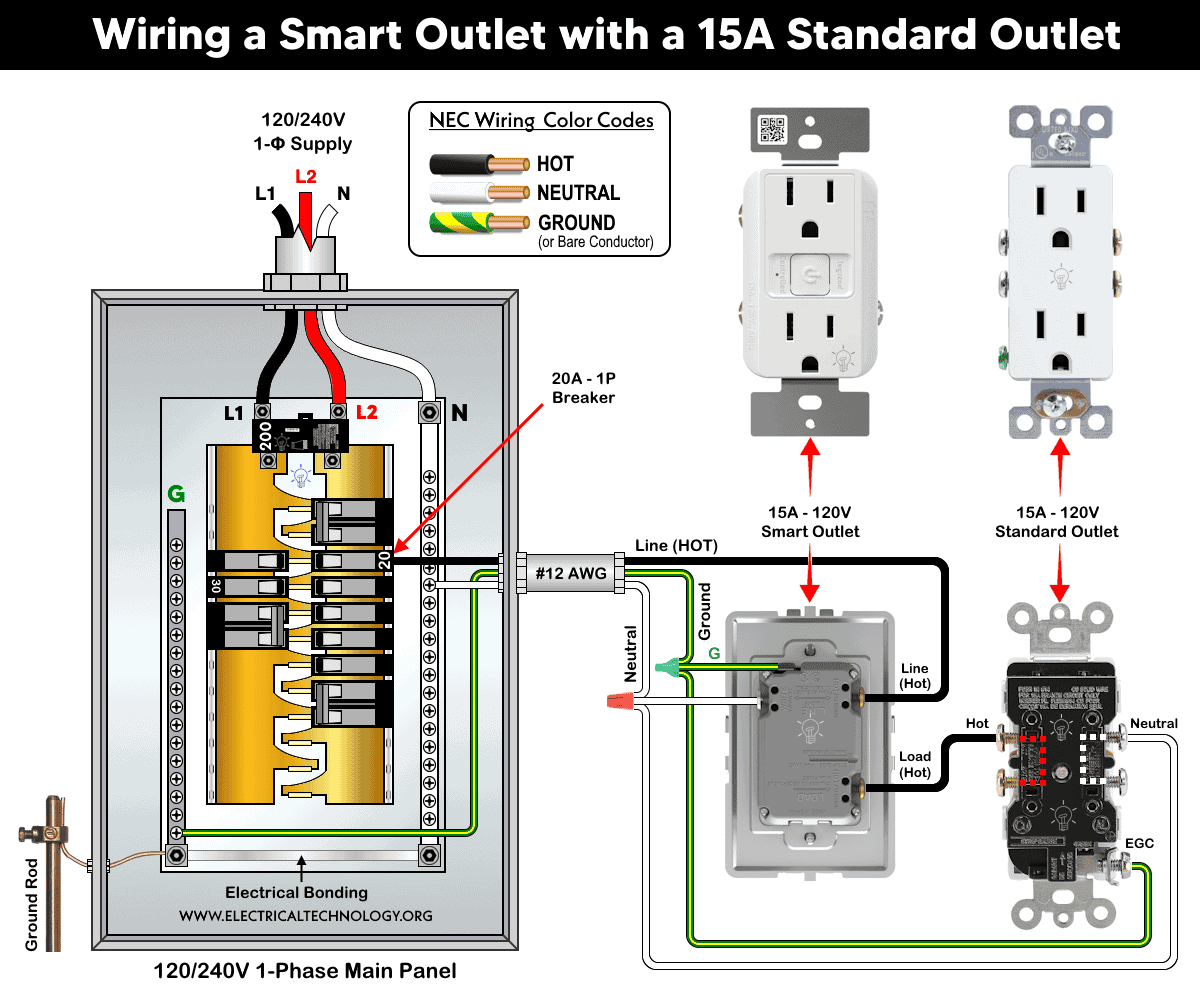
Terminate the #12 or #14 AWG branch circuit conductors in box 1 to the smart receptacles as follow:
- Ungrounded (Hot) Conductor: Black conductor to brass or black terminal screw.
- Grounded (Neutral) Conductor: White conductor to silver terminal screw.
- Equipment Grounding Conductor (EGC): Bare copper or green (or green/yellow-striped) conductor to green grounding screw.
Now, connect the load side terminal of smart outlet to the brass screw of standard 15A outlet in box 2. Connect the neutral and ground wires someway as shown in the wiring diagram.
For Wi-Fi lighting control, including scheduling and remote ON/OFF operation, use the My Leviton app for Leviton Decora Smart devices. For the Radiant® Smart Wi-Fi Outlet by Legrand, use the Home + Control app. Both applications are available on the Google Play Store (Android) and Apple App Store (iOS). After completing the installation, open the appropriate app and follow the on-screen instructions to add your new device. Once the setup process is complete, you will be able to control the device’s ON/OFF control or scheduling function remotely using your smartphone.
Instructions & Precautions
- Use #14 AWG for 15A circuit and #12 AWG for 20A circuits.
- Strip the insulation as per requirement given in the back side or sticker printed on the device.
- Terminate the screw as per given torquing on the device nameplate.
- A 15A outlet can’t and shouldn’t be used for 20A load.
- Per NEC Table – 310.16 , 210.24.(1) and 240.4(D)(4), the correct breaker and wire size for a 15-Amp, 125V (NEMA 5-15R) outlet is #14 AWG copper or #12 AWG Aluminum.
- Use #14/2 cable (hot wire, a neutral and one ground) for a 15A-120V breaker and receptacle/outlet.
- A 15A outlet can be used for a 12A continuous load and a maximum 15A non-continuous load (210.19(A)), 215.2, and 230.42(A).
- 15A, 120V outlet and receptacles should be installed on 15 amp breaker only.
Resources:
Smart Devices Wiring Series
- How to Wire 120/240V Smart Load Center with Smart Breakers
- How to Wire a Smart Breaker in a Smart 120/240V Panel
- How to Wire a Smart GFCI Breaker in a 120/240V Smart Panel
- How to Wire Smart AFCI/GFCI Breaker in a Smart Load Center
Main Panels Wiring Tutorials
- How to Wire 120/240V Main Panel – Breaker Box Installation
- How to Wire 120V/208V, 1-Phase & 3-Phase Main Panel?
- How to Wire 120/208/240V High Leg Delta 1-Phase & 3-Phase Main Panel?
- How to Wire 277/480V, 1-Phase & 3-Phase Main Service Panel?
- How to Wire 347/600V, 1 and 3-Phase Main Service Panel?
- How to Wire a Subpanel? Main Lug Installation for 120V/240V
- How to Wire a Spa Panel Box for a Hot Tub using 2P GFCI & Breaker
- Single Phase Electrical Wiring Installation in Home – NEC & IEC
- Three Phase Electrical Wiring Installation in Home – NEC & IEC
- How To Wire a Single Phase kWh Meter – 120V/240V
- How to Wire a Three-Phase Meter? 120/208/240/277/347/480/600V
Wiring Smart / Standard GFCI & Breakers
- How to Wire a 1-Pole Breaker
- How to Wire a 2-Pole Breaker
- How to Wire a 3-Pole Breaker
- How to Wire a 1-Pole GFCI
- How to Wire a 2-Pole GFCI
- How to Wire a 3-Phase, 3-Pole GFCI
- How to Wire a Tandem Breaker
- How to Wire GFCI Circuit Breakers
- How to Wire an AFCI Breaker
Wiring Smart / General Outlets & GFCI/AFCI Receptacles
- How to Wire an Outlet Receptacle? Socket Outlet Wiring Diagrams
- How to wire a GFCI Outlet?
- How to a Wire 3-Way Combination Switch and Grounded Outlet?
- How to Wire a 15A – 125V Outlet – NEMA 5-15 Receptacle
- How to Wire a 20A – 125V Outlet – NEMA 5-20 Receptacle
- How to Wire a 15A – 250V Outlet – NEMA 6-15 Receptacle
- How to Wire a 20A – 250V Outlet – NEMA 6-20 Receptacle
- How to Wire a 50A – 125/250V Outlet – NEMA 14-50 Receptacle
Switches Wiring
- How to Wire Single Pole, Single Throw (SPST) as 2-Way Switch?
- How to Wire Single Pole, Double Throw (SPDT) as 3-Way Switch?
- How to Wire Double Pole, Single Throw Switch? Wiring DPST
- How to Wire Double Pole, Double Throw Switch? Wiring DPDT
- How to Wire Double Switch? 2-Gang, 1-Way Switch – IEC & NEC
- How to Wire 4-Way Switch (NEC) or Intermediate Switch as 3-Way (IEC)?
- How to Wire Auto & Manual Changeover & Transfer Switch – (1 & 3 Phase)
Sizing Breakers, Wires, and Panels
- How to Size a Load Center, Panelboards and Distribution Board?
- How to Determine the Right Size Capacity of a Subpanel?
- How to Find the Right Wire Size for 100A Service 120V/240V Panel?
- How to Size a Circuit Breaker?
- How to Find the Proper Size of Wire & Cable In Metric & Imperial Systems
- How to Size a Breaker and Wires in AWG with EGC for Load?
- How to Size Service-Entrance Conductors and Feeder Cables?
- How to Size Feeder Conductors with Overcurrent Protection
- How to Size a Branch Circuit Conductors with Protection?
- How to Size Equipment Grounding Conductor (EGC)?
- How to Size Grounding Electrode Conductor (GEC)?
- How to Size Main Bonding Jumper (MBJ)?
- How to Size Motors FLC, HP, Voltage, Breaker Size and Wire Size
- What is the Correct Wire Size for 100A Breaker and Load?
- What is the Right Wire Size for 15A Breaker and Outlet?
- What is the Suitable Wire Size for 20A Breaker and Outlet?
Finding the Number of Breakers/Outlets in a Circuit
- How to Determine the Number of Circuit Breakers in a Panelboard?
- How to Find the Number of Outlets on a Single Circuit Breaker?
- How to Find Voltage & Ampere Rating of Switch, Plug, Outlet & Receptacle
- How to Calculate the Number of Fluorescent Lamps in a Final Sub Circuit?
- How to Calculate the Number of Incandescent Lamps in a Final Sub Circuit?
- How to Determine the Number of Lighting Branch Circuits?
- How to Determine the Number of Branch Circuits? – 3 Ways
- How to Find the Number of Lights on a Single Circuit Breaker?
General Wiring Installation Tutorials:
- How to Toggle Electric Water Heater Between 120V and 240V?
- How to Wire 120V Water Heater Thermostat – Non-Simultaneous?
- How to Wire 240V Water Heater Thermostat – Non-Continuous?
- How to Wire 3-Phase Simultaneous Water Heater Thermostat?
- How to Wire Twin Timer for 120V/240V Circuits – ON/OFF Delay
- How to Wire ST01 Timer with Relay & Contactor for 120V/240V Motors?
- How to Wire Multifunction ON/OFF Delay Timer for 120V/240V Motors?
- Even More Residential Wiring Installation Tutorials