How to Wire a 3-Phase, 3-Pole GFCI Breaker in a 3-Φ Panel
How to Install a Three-Phase, 3-Pole GFCI Breaker with and without Neutral
A 3-phase, 3-pole Ground-Fault Circuit Interrupter (GFCI) breaker is used to provide ground-fault protection for three-phase loads supplied from a 120/208V, 3-phase, 4-wire wye (Y) o any other three-phase supply system. These breakers are commonly installed in commercial and industrial distribution panels to protect equipment such as motors, HVAC units, commercial kitchen appliances, pumps, and specialty receptacles located in wet or hazardous environments.
Unlike standard 3-pole circuit breakers, a 3-pole GFCI breaker continuously monitors the vector sum of current in all phase conductors (and neutral, if present). If an imbalance exceeding the GFCI trip threshold is detected, it indicates leakage current to the ground, hence, the GFCI breaker trips and disconnects all ungrounded conductors simultaneously.
Characteristics:
- Number of Poles: 3-pole – connects to three lines (L1, L2 & L3), i.e. all hot conductors Hot 1, Hot 2 & Hot 3 (black, red & blue). All lines are mechanically and electrically linked together.
- Voltage: Operates on and protects 208V, 240V, 480V, or 600V, three-phase branch circuits. (Line-to-Line).
- Amperage Rating: Commonly available in 15A to 100A with 65kA of interrupting rating and 5mA to 30mA protection in NEMA 1 & NEMA 3R outdoor enclosures.
- Wiring: Three hot conductors from the breaker, a ground wire (+ a neutral if required) from ground/neutral busbar connects to the three-phase branch circuit in a 120V or 240V supply. The built-in white pigtail on the GFCI breaker always connects to the neutral busbar in the main panel.
- Operation: Trips when there is an overload, short circuit, or ground-fault even on a single line and trips all ungrounded conductor(s) at once.
- Application: Used as per NEC requirement for heavy loads i.e. motors, HVAC, commercial countertops, welders, air-compressors, outlets/receptacles and industrial appliances, especially located in outdoor or wet areas.
NEC Requirements for GFCI Installation
NEC 210.8(A) requires ground-fault circuit-interrupter (GFCI) protection for branch circuits and receptacles installed in specific locations. These locations include, but are not limited to, bathrooms, garages, outdoor areas, basements, kitchens, laundry areas, pools, spas and other similar spaces as identified by the Code.
As per NEC 210.8(B) for non-dwelling units, all receptacles supplied by three-phase branch circuits rated 150V or less to ground and 100A or less must have GFCI protection.
Moreover, per NEC 210.8(D) for specific appliances, GFCI protection is required for branch circuits or outlets (including hardwired equipment) supplying specific appliances rated 150V or less to ground and 60A or less, whether they are single-phase or three-phase.
In addition, the NEC requires GFCI protection for various occupancies, equipment, and special installations throughout the Code. Relevant sections include, but are not limited to, Articles 210.8, 406.3, 424.44, 426.28, 427.22, 511.12, 517.17, 517.20, 525.23, 530.44, 547.28, 555.35, 620.6, 625.54, 680.5, 680.21, 680.22, 680.23, 680.27, 680.32, 680.43, 680.44, 680.51 through 680.59, 680.62, and 680.71.
Wiring a 3-Phase, 3-Pole GFCI Breaker
To install or replace a 3-Phase, 3-Pole GFCI breaker in a three-phase panelboard, follow the following simple steps.
Step 1: Disconnect the Main Power Supply
De-energize the panel and apply lockout/tagout before working. Verify absence of voltage on all bus bars using non-contact tester. Never touch incoming service lugs; they remain energized unless upstream disconnect is open.
Step 2: Verify Panel Configuration
Confirm that the panel is rated for 120/208V, 3-phase, 4-wire wye, 120/208/240V (High Leg) or any other three-phase supply systems such as 480V or 600V.
The three phase load center is equipped with three phase bus bars (A-B-C) viz L1, L2 & L3 and a neutral/ground bus bar where it is grounded and bonded at the service disconnect (not at subpanels).
Step 3: Install the 3-Pole GFCI Breaker
3-Pole GFCI breakers snap over 3 busbars and draw Hot from each busbar. Mount the breaker onto the A-B-C phase bus bars. Ensure the breaker seats fully and locks into place.
Step 4: Connect Phase Conductors (Load Side)
Connect the load conductors as follows:
- Phase A (L1) to the breaker terminal A
- Phase B (L2) to the breaker terminal B
- Phase C (L3) to the breaker terminal C
Tighten all terminals to the manufacturer’s specified torque.
Step 5: Ground & Neutral Connection (If Required)
For 208V, 3-phase loads, 3-pole, 3-wire without neutral, the neutral conductor does not run to the load.
For 208/240V, 3-phase, 3-pole, 4-wire loads with neutral, the neutral conductor from the breaker terminal (not from the neutral busbar) run to the load.
The bulti-in white or gray neutral pigtail in the GFCI is not a load neutral, it powers the GFCI electronics, hence, it must connects to the neutral busbar.
As a last wire connection, connect the Equipment Grounding Conductor (EGC) from the load to the ground bus bar in the 3-phase main panel.
Step 6: Test / Rest & Verify
Restore power and switch the breaker ON. Press the TEST button on the GFCI breaker to verify proper operation as it must trip immediately. Reset the breaker after successful testing.
Wiring Diagram of 3-Phase, 3-Pole, 3-Wire GFCI Breaker in a 3-Φ, 120/208V Panel
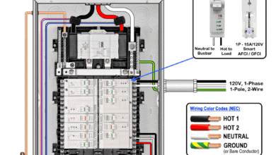
The following wiring diagram shows a 20A, 208V, 3-pole, 3-phase GFCI breaker without Neutral in a 120/208V panel used to protect a 208V three-phase appliance.
Click image or open in a new tab to enlarge

A 120/208V, 3-Phase 3-Wire Y panel offers:
- L1 to L2 = 208V – 1-Phase
- L2 to L3 = 208V – 1-Phase
- L1 to L3 = 208V – 1-Phase
- L1, L2 or L3 (Any 1 Hot) to Neutral = 120V – 1-Phase
- L1, L2 & L3 = 208V – Three-Phase
The color codes used for hot conductors in 120/208V are as follows:
- L1 = Black
- L2 = Red
- L3 = Blue
- Neutral = White / Grey
- Ground = Bare or Green/ with yellow stripe
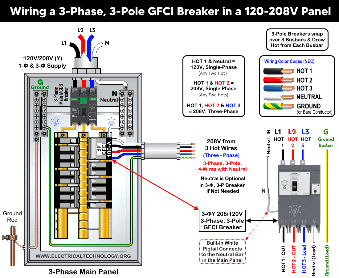
Wiring Diagram of 3-Phase, 3-Pole, 4-Wire GFCI Breaker in a 3-Φ, 120/208V Panel
The following wiring diagram shows a 100A, 208V, 3-pole, 3-phase GFCI breaker with Neutral used to protect a 208V three-phase branch circuit.
Click image or open in a new tab to enlarge
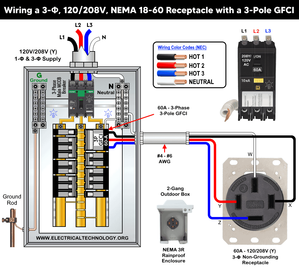
The same wiring configuration is used for connecting a NEMA 18-60 receptacle rated for 3-phase, 208Y/120V operation. The non-grounding receptacle is supplied through a 3-pole GFCI circuit breaker with a neutral conductor, as shown below.
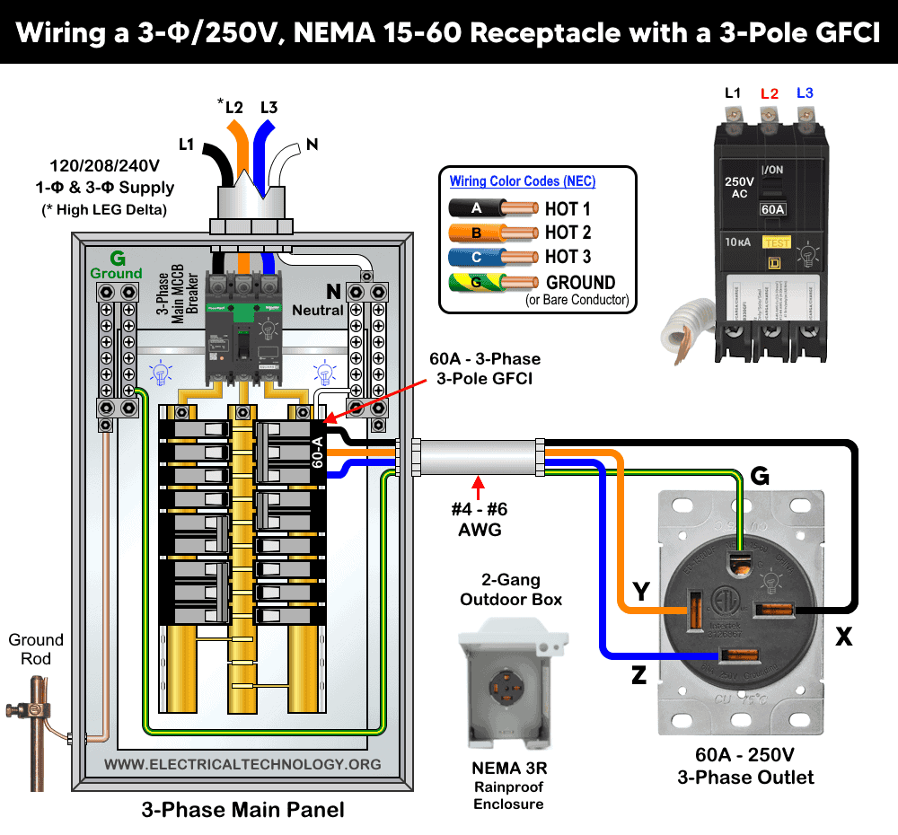
Wiring Diagram of 3-Phase, 3-Pole, 4-Wire GFCI Breaker in a 3-Φ, 120/208/240V (High Leg Delta) Panel
The following wiring diagram shows a 80A, 3-pole, 3-phase GFCI breaker with Neutral used in 120/208/240V (High Leg Delta) panel to protect a 240V three-phase load circuit.
Click image or open in a new tab to enlarge
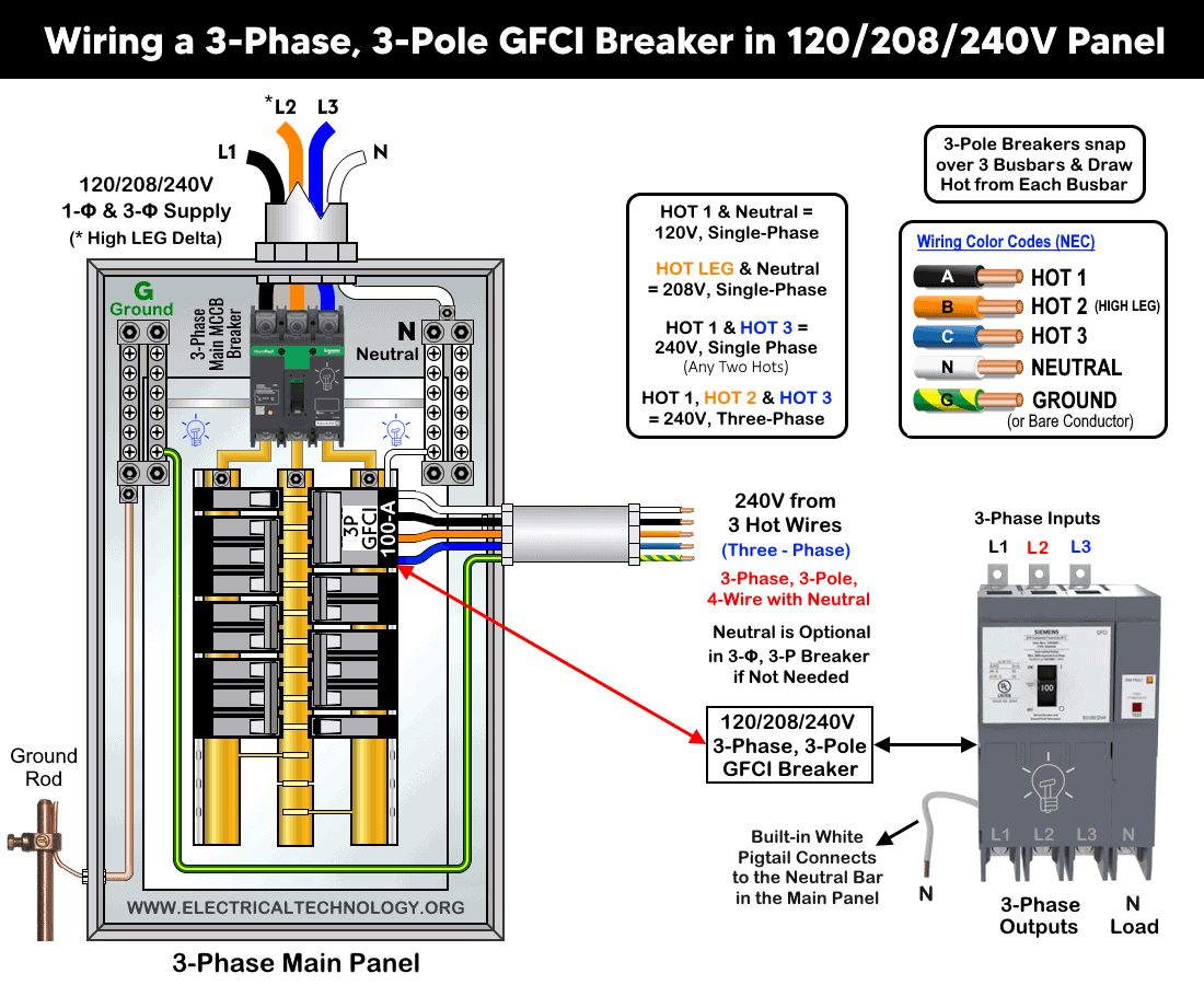
A High-Leg Delta (120/208/240V, 3-Phase 4-Wire) system offers:
- L1 to L2 = 240V – 1-Phase
- L2 to L3 = 240V – 1-Phase
- L1 to L3 = 240V – 1-Phase
- L1 or L3 to Neutral = 120V – 1-Phase
- L1, L2 & L3 = 240V – Three-Phase
- L2 (High Leg) to Neutral ≈ 208V – 1-Phase
The color codes used for hot conductors in 120/208/240V high leg delta are as follows:
- L1 = Black
- L2 = Orange (High or Wild Leg)
- L3 = Blue
- Neutral = White / Grey
- Ground = Bare or Green/ with yellow stripe
In addition, the following wiring configuration illustrates the connection of a NEMA 15-60 receptacle rated for three-phase, 120/208/240V operation. The receptacle is supplied through a three-pole GFCI circuit breaker, with no neutral conductor, as shown below.
Instructions, Precautions & Codes
- The suitable wire size for phase conductors is determined using NEC Table – 310.16.
- The equipment grounding conductor (EGC) is sized based on NEC Table 250.122.
- The breaker rating and size must match or exceed calculated load or receptacles per NEC Article 210.21(B)(2) & 430 (if motor circuits).
- With a 3-pole breaker/GFCI, the appropriate cable types include THHN/THWN-2 (Copper, Aluminum or Copper-Clad Aluminum). Use THHN/THWN-2 for indoor (conduit), THWN-2 or XHHW-2 for outdoor or wet locations, or SOOW flexible cord (indoor/outdoor), Type SER or MC cable for feeder cable and Type UF-B or USE-2 for underground feeder.
Resources:
Standard Breakers & GFCI Breakers Wiring Installations
- How to Wire a 1-Pole GFCI
- How to Wire a 2-Pole GFCI
- How to Wire a 3-Phase, 3-Pole GFCI Breaker … You are Here
- How to Wire a 1-Pole Breaker
- How to Wire a 2-Pole Breaker
- How to Wire a 3-Pole Breaker
- How to Wire a Tandem Breaker
- How to Wire GFCI Circuit Breakers
- How to Wire an AFCI Breaker
Sizing Breakers, Wires, and Panels
- How to Size a Circuit Breaker?
- How to Size a Breaker and Wires in AWG with EGC for Load?
- How to Find the Proper Size of Wire & Cable In Metric & Imperial Systems
- How to Size a Load Center, Panelboards and Distribution Board?
- How to Determine the Right Size Capacity of a Subpanel?
- How to Find the Right Wire Size for 100A Service 120V/240V Panel?
- How to Size Service-Entrance Conductors and Feeder Cables?
- How to Size Feeder Conductors with Overcurrent Protection
- How to Size a Branch Circuit Conductors with Protection?
- How to Size Equipment Grounding Conductor (EGC)?
- How to Size Grounding Electrode Conductor (GEC)?
- How to Size Motors FLC, HP, Voltage, Breaker Size and Wire Size
- What is the Correct Wire Size for 100A Breaker and Load?
- What is the Right Wire Size for 15A Breaker and Outlet?
- What is the Suitable Wire Size for 20A Breaker and Outlet?
General Outlets and GFCI/AFCI Receptacles Wiring
- How to Wire an Outlet Receptacle? Socket Outlet Wiring Diagrams
- How to wire a GFCI Outlet?
- How to Wire GFCI Combo Switch and Outlet
- How to Wire an AFCI Combo Switch
- How to Wire an AFCI Outlet?
- How to a Wire 3-Way Combination Switch and Grounded Outlet?
- How to Wire Combo Switch and Outlet? – Switch/Outlet Combo Wiring Diagrams
- How to Wire a 15A – 120V Outlet – NEMA 5-15 Receptacle
- How to Wire a 20A – 120V Outlet – NEMA 5-20 Receptacle
- How to Wire a 15A – 240V Outlet – NEMA 6-15 Receptacle
- How to Wire a 20A – 240V Outlet – NEMA 6-20 Receptacle
- How to Wire a 50A – 125/250V Outlet – NEMA 14-50 Receptacle
Switches Wiring
- How to Wire Single Pole, Single Throw (SPST) as 2-Way Switch?
- How to Wire Single Pole, Double Throw (SPDT) as 3-Way Switch?
- How to Wire Double Pole, Single Throw Switch? Wiring DPST
- How to Wire Double Pole, Double Throw Switch? Wiring DPDT
- How to Wire Double Switch? 2-Gang, 1-Way Switch – IEC & NEC
- How to Wire 4-Way Switch (NEC) or Intermediate Switch as 3-Way (IEC)?
- How to Wire Auto & Manual Changeover & Transfer Switch – (1 & 3 Phase)
Finding the Number of Breakers/Outlets in a Circuit
- How to Determine the Number of Circuit Breakers in a Panelboard?
- How to Find the Number of Outlets on a Single Circuit Breaker?
- How to Find Voltage & Ampere Rating of Switch, Plug, Outlet & Receptacle
- How to Calculate the Number of Fluorescent Lamps in a Final Sub Circuit?
- How to Calculate the Number of Incandescent Lamps in a Final Sub Circuit?
- How to Determine the Number of Lighting Branch Circuits?
- How to Determine the Number of Branch Circuits? – 3 Ways
- How to Find the Number of Lights on a Single Circuit Breaker?
Main Panels Wiring Tutorials
- How to Wire 120V/240V Main Panel? Breaker Box Installation
- How to Wire 208V/120V, 1-Phase & 3-Phase Main Panel?
- How to Wire 240V, 208V & 120V, 1 & 3-Phase, High Leg Delta Main Panel?
- How to Wire 277V/480V, 1-Phase & 3-Phase Main Service Panel?
- How to Wire a Subpanel? Main Lug Installation for 120V/240V
- Single Phase Electrical Wiring Installation in Home according to NEC & IEC
- Three Phase Electrical Wiring Installation in Home – NEC & IEC
- How To Wire a Single Phase kWh Meter – 120V/240V
- How to Wire a Three-Phase Meter? 120/208/240/277/347/480/600V
General Wiring Installation Tutorials:
- How to Toggle Electric Water Heater Between 120V and 240V?
- How to Wire 120V Water Heater Thermostat – Non-Simultaneous?
- How to Wire 240V Water Heater Thermostat – Non-Continuous?
- How to Wire 3-Phase Simultaneous Water Heater Thermostat?
- How to Wire Twin Timer for 120V/240V Circuits – ON/OFF Delay
- How to Wire ST01 Timer with Relay & Contactor for 120V/240V Motors?
- How to Wire Multifunction ON/OFF Delay Timer for 120V/240V Motors?
- Even More Residential Wiring Installation Tutorials
Related Posts:
- Difference Between Circuit Breaker and GFCI
- Difference Between 1-Pole and 2-Pole Breakers – NEC & IEC
- Should GFCI Protection Be in the Main Panel or Receptacle?
- How Does a Standard Breaker Respond to Electrical Fault?
- Why Doesn’t a Standard Breaker Protract Against Ground Faults?
- How Do GFCI and Standard Breakers Respond to Ground Faults?
- Can you use 15A Breaker on 20A Circuit and Vice Versa?
- Can I Use a 1-Phase Breaker on a 3-Phase Supply & Vice Versa?
- Can I Use a 240V Breaker on a 120V Circuit and Vice Versa?
- Can You use a 15A Outlet on a 20A Circuit and Vice Versa?