How to Wire 15A and 20A Wi-Fi Smart GFCI Outlets
How to Wire a Smart GFCI Outlet – Wiring a 15A/20A Wi-Fi GFCI Receptacle in Smart and Standard 120/240V Panels
Wi-Fi Smart GFCI outlets and receptacles enhance your home’s electrical safety while giving you complete peace of mind. When a ground fault is detected or the device trips, the Wi-Fi GFCI receptacle instantly sends a notification to your smartphone.
The Leviton smart GFCI receptacles combines advanced ground-fault protection with real-time mobile alerts through the My Leviton app. The app provides clear status visibility for normal operation, ground-fault events, and test mode. Although, it is for smart home automation, it intentionally excluded remote ON/OFF control of the GFCI outlet to maintain safety and code compliance.
The innovative Wi-Fi outlets is an ideal for refrigerators, sump pumps, and appliances in garages, basements, or second homes. These outlets are better choice to enhances protection in areas where routine checks are uncommon. Moreover, it also features an optional audible alarm and integrates seamlessly with other Decora Smart devices, supporting a connected, whole-home electrical monitoring solution.
What is a GFCI & Where to Install it?
A Ground-Fault Circuit Interrupter (GFCI) is a protective device which monitors current between hot and neutral and trips if an imbalance (ground fault) occurs. It will disconnect the power supply to the device to protect against shock hazards.
The NEC – 210.8(A) requires GFCI protection in areas of the home where moisture or grounding risks are present, including kitchens, bathrooms, laundry rooms, workshops, basements, garages, carports, and outdoor spaces such as pools, decks, and patios. GFCI outlets protect not only the devices plugged directly into them but also provide feed-through protection to standard outlets connected downstream on the same circuit.
Rating & Features of a Smart GFCI Outlets
- Name: Smart Wi-Fi GFCI Outlet / Receptacles – NEMA 5-15 & NEMA 5-20
- Poles: 2-Poles, 3 Wires Grounding
- Voltage: 125V Single-Phase AC Supply – 60 Hz
- Current: 15A & 20A
- Wattage: 1 HP Motor
- Trip Level: Class A, 5mA ± 1mA
- Short Circuit Current Rating: 10kA
- Wire Size: #14 & #12 AWG Copper
- Termination: Back & Side Wiring
- Compatibility: With all Decora devices and My Leviton App.
Wiring a 15A Wi-Fi Smart GFCI Outlet in a Smart Panel
Before proceeding, switch OFF the main breaker at the main panel to confirm power is off.
To install or replace existing GFCI outlet, make sure the current outlet is on a 15A/120V circuit protected by a 15A single-pole breaker and #14AWG branch circuit conductors.
1. Identify LINE vs LOAD Wires
Smart GFCI devices have two connection terminals:
- LINE terminals – power coming from the breaker panel
- LOAD terminals – power going to downstream outlets
Before wiring, you must identify which cable is LINE and which is LOAD (which is clearly mentioned on the back side of the device beside the screws.
2. Strip and Termination of Wires:
For side wiring, strip 3/4″ (19 mm) of insulation from the ends of all conductors. Form a small hook (in J shape) in each conductor if wrapping around terminal screws. For back wiring, strip 5/8″ (16 mm) of insulation from the ends of all conductors.
Connect the wires as per terminal color coding as:
- Brass/Black Screw = HOT Conductor
- Silver = NEUTRAL Conductor
- Green = GROUND Conductor
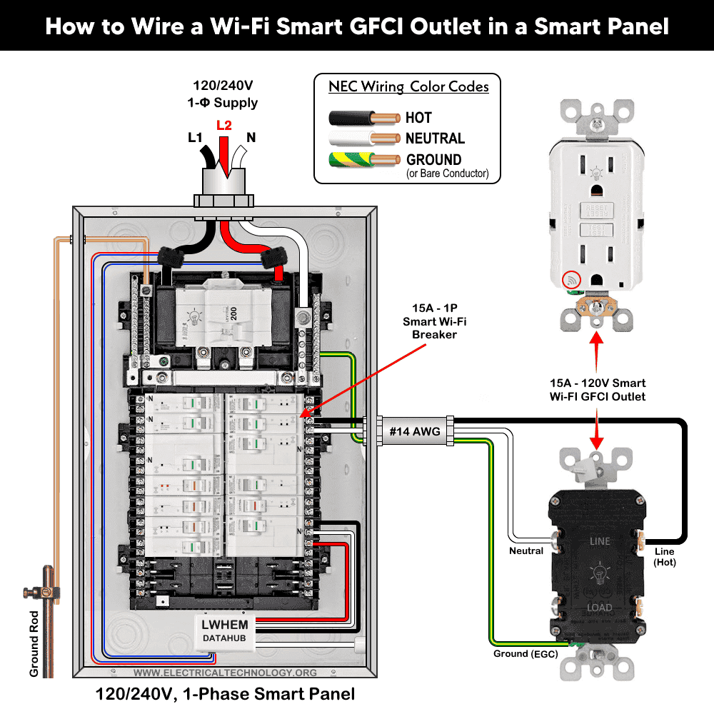
3. Only LINE Connection (Required)
- Connect the incoming hot (black) to the Brass “LINE” terminal.
- Connect the incoming neutral (white) to the Silver “LINE” terminal.
- Connect the bare/green grounding wire to the GFCI’s green screw.
Tighten the screws approximately 14-18 in·lbs (1.6-2 N·m) of torque.
Do not remove the yellow LOAD sticker yet as the load terminals are optional (not needed if only want to install single GFCI outlet). Those (load) terminals will be used in second wiring (given below) when downstream outlets / devices are connected to the GFCI outlet.
4. Mount the Outlet
Gently fold wires and carefully place the device into the electrical box. Fasten the GFCI with the screws and attach the cover plate.
5. Power On & Test Operation
Turn ON the main breaker and switch-on the breaker associated with outlet at the panel.
- Press the RESET button until it clicks. If wired correctly and powered, the Status LED should light solid GREEN (indicating normal operation).
- If the device does not reset or the LED doesn’t light, check that LINE and LOAD are not reversed. A miswire lockout will prevent reset.
- Press the TEST button, the outlet should trip and cut power. Press RESET again. This confirms proper functionality.
The following wiring diagram shows a 15A, 120V smart GFCI outlet (Decora D2GF1-KW) is supplied through a 15A, single-pole (1P) Wi-Fi smart breaker installed in a smart 120V/240V panel by Leviton.
Click image or open in a new tab to enlarge
Smart GFCI has diagnostic status LED indicator:
Wiring a 20A Smart GFCI Outlet with a Standard Outlet
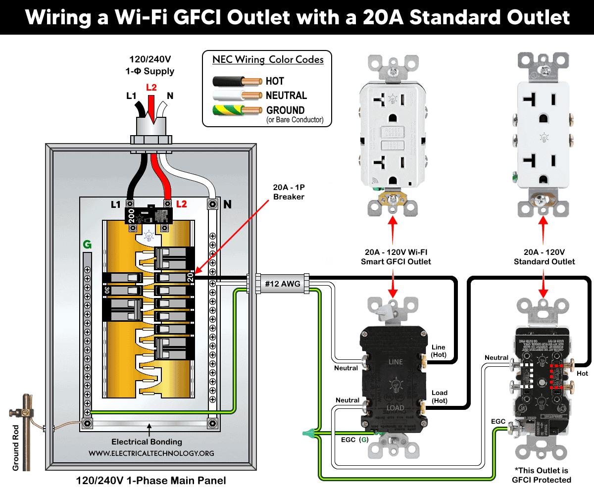
As the line side wiring is same as shown above for 15A GFCI wiring diagram, we will proceed from the load side terminals.
As the LOAD connection are optional and only used when you want downstream outlets protected by the GFCI. To do so:
Remove yellow sticker covering LOAD terminals.
- Connect outgoing hot to Brass “LOAD” terminal on GFCI. The outgoing hot wire then connects to the brass screw terminal of standard outlet.
- Connect outgoing neutral to Silver “LOAD” terminal of GFCI. Similarly, the outgoing neutral from the GFCI goes and connects to the silver terminal on the standard 20A outlet.
- Connect all bare/green grounding wires together and to the GFCI’s green screw.
The following wiring diagram illustrates a 20A/120V smart GFCI receptacle is wired with a conventional 20A outlet supplied by a 20A, 1P breaker in the main 120V/240V panel using #12AWG branch circuit conductors.
Click image or open in a new tab to enlarge
Smart Control
For smart notifications, use the My Leviton app with Leviton Decora Smart devices. For safety reasons, ON/OFF control of the smart GFCI outlet is intentionally disabled in the app. In addition, you may enable or disable the built-in audible trip alert in the app.
After completing installation, open the app and follow the on-screen instructions to add your new device. Once setup is complete, you will receive remote notifications on your smartphone if the device trips due to a ground fault.
Instructions & Precautions.
- Use #14 AWG for 15A circuit and #12 AWG for 20A circuits.
- Strip the insulation as per requirement given in the back side or sticker printed on the device.
- Terminate the screw as per given torquing on the device nameplate.
- A 15A outlet can’t and shouldn’t be used for 20A load.
- Use #14/2 cable (hot wire, a neutral and one ground) for a 15A-120V breaker and receptacle/outlet.
- Use #12/2 cable (hot wire, a neutral and one ground) for a 20A-120V breaker and receptacle/outlet.
- A 15A load can be connected to a 20A outlet. It is permissible to use 15A receptacles if there are two or more receptacles (such as duplex) on a 20A circuit.
- It is NOT code to connect 20A load on a 15A outlet. In addition, A 20A plug will not fit into a 15A receptacle, and attempting to force it in is dangerous.
- A standard 20A outlet accepts both 15A and 20A plugs (non-T-slot), but not vice versa.
- 15A, 120V outlet and receptacles should be installed on 15 amp breaker only. Similarly, a 20A, 120V outlet must be installed only on a 20A circuit breaker.
Resources:
Smart Devices Wiring Series
- How to Wire 120/240V Smart Load Center with Smart Breakers
- How to Wire a Smart Breaker in a Smart 120/240V Panel
- How to Wire a Smart GFCI Breaker in a 120/240V Smart Panel
- How to Wire Smart AFCI/GFCI Breaker in a Smart Load Center
- How to Wire a 15A Wi-Fi Smart Outlet in a Smart Panel
- How to Wire a Smart Switch in a 120/240V Load Center
Main Panels Wiring Tutorials
- How to Wire 120/240V Main Panel – Breaker Box Installation
- How to Wire 120V/208V, 1-Phase & 3-Phase Main Panel?
- How to Wire 120/208/240V High Leg Delta 1-Phase & 3-Phase Main Panel?
- How to Wire 277/480V, 1-Phase & 3-Phase Main Service Panel?
- How to Wire 347/600V, 1 and 3-Phase Main Service Panel?
- How to Wire a Subpanel? Main Lug Installation for 120V/240V
- How to Wire a Spa Panel Box for a Hot Tub using 2P GFCI & Breaker
- Single Phase Electrical Wiring Installation in Home – NEC & IEC
- Three Phase Electrical Wiring Installation in Home – NEC & IEC
- How To Wire a Single Phase kWh Meter – 120V/240V
- How to Wire a Three-Phase Meter? 120/208/240/277/347/480/600V
Wiring Smart / Standard GFCI & Breakers
- How to Wire a 1-Pole Breaker
- How to Wire a 2-Pole Breaker
- How to Wire a 3-Pole Breaker
- How to Wire a 1-Pole GFCI
- How to Wire a 2-Pole GFCI
- How to Wire a 3-Phase, 3-Pole GFCI
- How to Wire a Tandem Breaker
- How to Wire GFCI Circuit Breakers
- How to Wire an AFCI Breaker
Wiring Smart / General Outlets & GFCI/AFCI Receptacles
- How to Wire an Outlet Receptacle? Socket Outlet Wiring Diagrams
- How to wire a GFCI Outlet?
- How to a Wire 3-Way Combination Switch and Grounded Outlet?
- How to Wire a 15A – 125V Outlet – NEMA 5-15 Receptacle
- How to Wire a 20A – 125V Outlet – NEMA 5-20 Receptacle
- How to Wire a 15A – 250V Outlet – NEMA 6-15 Receptacle
- How to Wire a 20A – 250V Outlet – NEMA 6-20 Receptacle
- How to Wire a 50A – 125/250V Outlet – NEMA 14-50 Receptacle
Switches Wiring
- How to Wire Single Pole, Single Throw (SPST) as 2-Way Switch?
- How to Wire Single Pole, Double Throw (SPDT) as 3-Way Switch?
- How to Wire Double Pole, Single Throw Switch? Wiring DPST
- How to Wire Double Pole, Double Throw Switch? Wiring DPDT
- How to Wire Double Switch? 2-Gang, 1-Way Switch – IEC & NEC
- How to Wire 4-Way Switch (NEC) or Intermediate Switch as 3-Way (IEC)?
- How to Wire Auto & Manual Changeover & Transfer Switch – (1 & 3 Phase)
Sizing Breakers, Wires, and Panels
- How to Size a Load Center, Panelboards and Distribution Board?
- How to Determine the Right Size Capacity of a Subpanel?
- How to Find the Right Wire Size for 100A Service 120V/240V Panel?
- How to Size a Circuit Breaker?
- How to Find the Proper Size of Wire & Cable In Metric & Imperial Systems
- How to Size a Breaker and Wires in AWG with EGC for Load?
- How to Size Service-Entrance Conductors and Feeder Cables?
- How to Size Feeder Conductors with Overcurrent Protection
- How to Size a Branch Circuit Conductors with Protection?
- How to Size Equipment Grounding Conductor (EGC)?
- How to Size Grounding Electrode Conductor (GEC)?
- How to Size Main Bonding Jumper (MBJ)?
- How to Size Motors FLC, HP, Voltage, Breaker Size and Wire Size
- What is the Correct Wire Size for 100A Breaker and Load?
- What is the Right Wire Size for 15A Breaker and Outlet?
- What is the Suitable Wire Size for 20A Breaker and Outlet?
Finding the Number of Breakers/Outlets in a Circuit
- How to Determine the Number of Circuit Breakers in a Panelboard?
- How to Find the Number of Outlets on a Single Circuit Breaker?
- How to Find Voltage & Ampere Rating of Switch, Plug, Outlet & Receptacle
- How to Calculate the Number of Fluorescent Lamps in a Final Sub Circuit?
- How to Calculate the Number of Incandescent Lamps in a Final Sub Circuit?
- How to Determine the Number of Lighting Branch Circuits?
- How to Determine the Number of Branch Circuits? – 3 Ways
- How to Find the Number of Lights on a Single Circuit Breaker?
General Wiring Installation Tutorials:
- How to Toggle Electric Water Heater Between 120V and 240V?
- How to Wire 120V Water Heater Thermostat – Non-Simultaneous?
- How to Wire 240V Water Heater Thermostat – Non-Continuous?
- How to Wire 3-Phase Simultaneous Water Heater Thermostat?
- How to Wire Twin Timer for 120V/240V Circuits – ON/OFF Delay
- How to Wire ST01 Timer with Relay & Contactor for 120V/240V Motors?
- How to Wire Multifunction ON/OFF Delay Timer for 120V/240V Motors?
- Even More Residential Wiring Installation Tutorials