Wiring Z-Wave Smart Switch, Dimmer & Fan Speed Controller
How to Wire a Z-Wave 800 Series Smart Switch, Dimmer and Fan Speed Controller with Neutral Wire Connection
What is a Smart Z-Wave Switch?
A Smart Z‑Wave 800 series 15A switch (such as ZW15S, ZW6HD, and ZW4SF by Leviton) is an in-wall smart switch that allows lighting and electrical loads to be controlled through a Z-Wave smart-home network and compatible hub. It replaces a standard wall switch and can be operated manually, through a mobile app, or by voice control when connected to a smart home system.
The switch is rated for 15A at 120V AC for general loads in single-pole or 3-way configurations. It supports 5A LED/CFL loads, 15A magnetic ballast, 1500 W incandescent or halogen lighting, and motors up to ¾ HP. These ratings allow it to control lighting, ceiling fans, exhaust fans, pumps, and other residential loads.
The Z-Wave smart switch can be paired with another smart switch companion devices (such as DD0SR, DD0SR-DLZ and DD00R etc.), to control the switch operation from another location. They can be used for scheduling (i.e. turn ON/OFF exterior lights at sunrise/sunset. In short, these switches can be controlled from anywhere using a compatible Z-Wave hub.
It also supports 8th generation wireless Z-Wave mesh networking and any other Z-Wave enabled network (Z-Wave Plus Network – 908.40, 908.42, 916.00 MHz). These features allows the smart devices to communicate with each other and extend network reliability.
The main advantages of Z-Wave® smart switch is remote control, scheduling, and voice automation when connected to a compatible Z-Wave hub. The switch can also act as a repeater to strengthen the Z-Wave mesh network. These switches are suitable option for smart lighting control in homes, energy management, security lighting automation, and multi-location lighting control using a companion switch(es).
How to Wire a Z-Wave Smart Device
A Z-Wave smart switch is installed by replacing an existing wall switch and connecting the circuit conductors to the switch leads.
In the following wiring tutorial, we will show how to wire the following Z-Wave smart devices:
- Z-Wave 800 Series Smart Switch (ZW15S)
- Z-Wave 800 Series Smart Dimmer Switch (ZW6HD)
- Z-Wave Plus Smart Fan Speed Controller (ZW4SF)
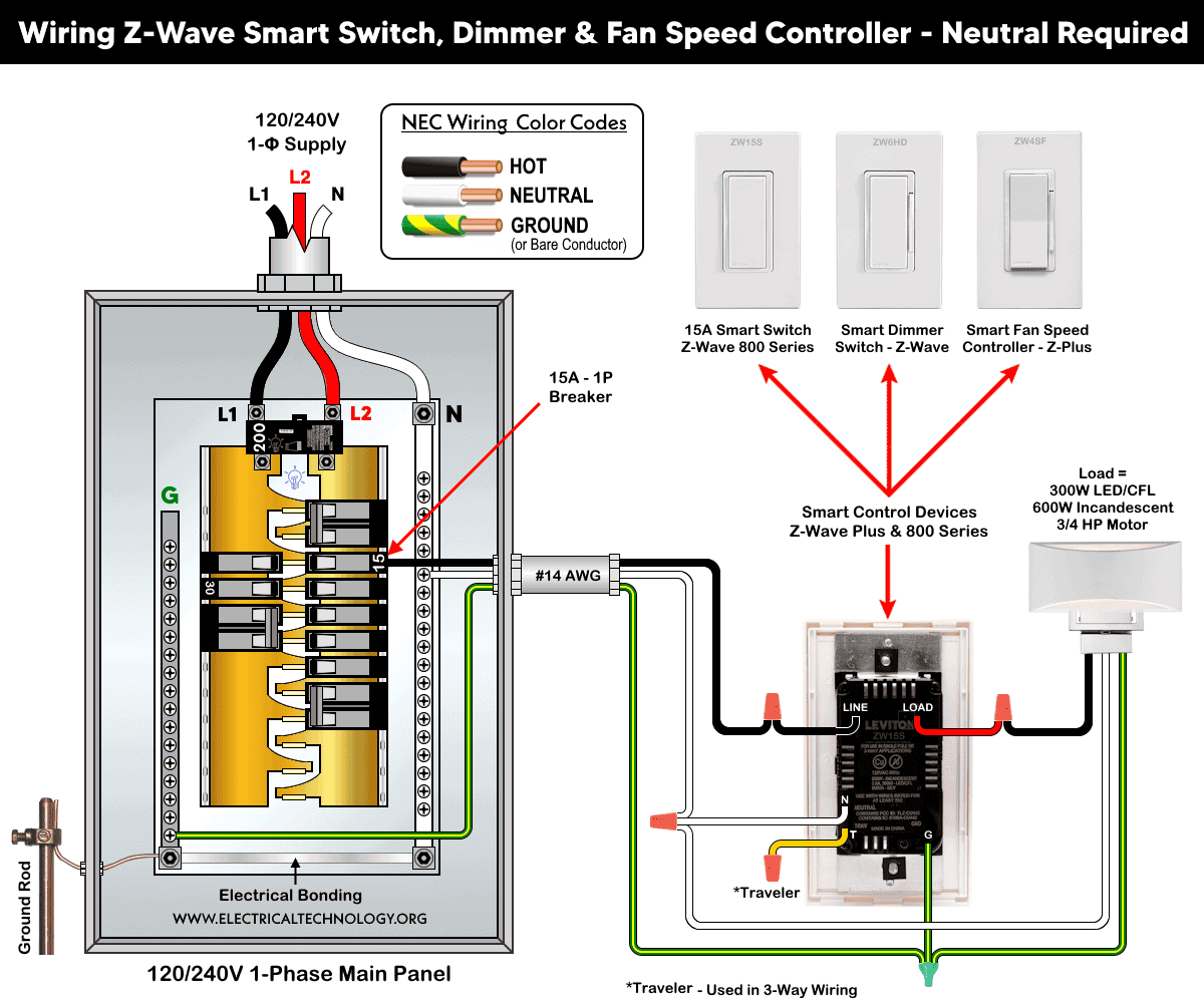
The wiring configuration is identical for all of these devices, and a neutral wire must be available in the wall box for proper operation. For reliable operation, the smart device should be installed within 50 ft (15 m) of the hub or another Z-Wave-enabled repeater.
For a single load application, the required connections are line (hot – black wire), load (red wire), neutral (white – wire), a traveler (T terminal used for 3-way switching) and ground (bare copper or green) wires in the wall box. The line wire supplies power to the switch, the load wire goes to the light or device, the neutral wire powers the smart electronics, and the ground wire provides safety grounding.
For a single-pole installation,
- Connect the line (hot) conductor (black wire) from branch circuit conductors to the switch “Line” lead.
- Tie the neutral (white) wires together with the switch neutral lead “N”.
- Connect the load wire from light (black wire) to the “Load” lead (red wire) via a wire-nut.
- Connect the equipment grounding conductor (ground wire) to the ground terminal.
- Put a wire-nut on the traveler (Yellow/Red) lead as it is not used in single load application.
After wiring, mount the switch in the wall box, restore power, and pair the device with a compatible Z-Wave hub.
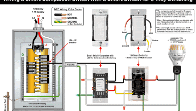
For 3-way or multi-location control, the smart switch is installed in one box and paired with a compatible wired companion switch. The companion communicates with the main switch through traveler wiring, which allows the same light to be controlled from multiple locations.
Wiring diagram of a smart control device (Z-Wave/ Plus & 800 Series) as a smart switch, dimmer switch or smart fan speed controller
Click image or open in a new tab to enlarge
Adding Device to the Network and Hub
The Smart Z-Wave 800 Series switch supports SmartStart. It can be included in a Z-Wave network by scanning the QR code or entering the PIN code located on the front, back, or device strap. After the device is powered on, it will automatically join the network within 10 minutes.
To enter setup mode, press and hold the top rocker for 7 seconds until the status LED turns amber. Release the rocker; the status LED will blink amber, indicating that the device has entered setup mode.
To exit setup mode and return to normal operation, repeat the same process until the LED turns amber again.
To add the smart switch to a Z-Wave hub network, enter setup mode as described above. Put the Z-Wave controller into inclusion mode according to the controller instructions. Tap the rocker once; the status LED will flash green, and the controller will confirm that the device has been successfully included in the Z-Wave network.
To remove the device from the network, repeat the same process as shown for inclusion expect removing the device from the network as per controller instructions.
Instructions & Precautions.
- Always disconnect the power supply by switching OFF the circuit breaker at the main service panel before performing any electrical work.
- According to NEC Tables 310.16, 210.24(1), and 240.4(D)(4), the correct breaker and conductor size for a 15A, 120V circuit is #14 AWG copper. Therefore, use #14 AWG copper or copper-clad conductors with 15A smart switches, breakers and receptacles.
- 15A/120V switches and receptacles must be installed on a 15-amp breaker only.
- Smart devices are intended for indoor use only.
- If you are unsure about any part of the installation, consult a licensed electrician and ensure compliance with applicable local electrical codes.
Disclaimer:
The author assumes no responsibility for any loss, injury, or damage resulting from the use or misuse of this information, including improper circuit installation. Electrical work can be hazardous. Always exercise extreme caution when working with electricity.
Resources:
Smart Devices Wiring Series
- How to Wire 120/240V Smart Load Center with Smart Breakers
- How to Wire a Smart Breaker in a Smart 120/240V Panel
- How to Wire a Smart GFCI Breaker in a 120/240V Smart Panel
- How to Wire Smart AFCI/GFCI Breaker in a Smart Load Center
- How to Wire a 15A Wi-Fi Smart Outlet in a Smart Panel
- How to Wire 15A and 20A Wi-Fi Smart GFCI Outlets
- How to Wire a Smart Switch in a 120/240V Load Center
Main Panels Wiring Tutorials
- How to Wire 120/240V Main Panel – Breaker Box Installation
- How to Wire 120V/208V, 1-Phase & 3-Phase Main Panel?
- How to Wire 120/208/240V High Leg Delta 1-Phase & 3-Phase Main Panel?
- How to Wire 277/480V, 1-Phase & 3-Phase Main Service Panel?
- How to Wire 347/600V, 1 and 3-Phase Main Service Panel?
- How to Wire a Subpanel? Main Lug Installation for 120V/240V
- How to Wire a Spa Panel Box for a Hot Tub using 2P GFCI & Breaker
- Single Phase Electrical Wiring Installation in Home – NEC & IEC
- Three Phase Electrical Wiring Installation in Home – NEC & IEC
- How To Wire a Single Phase kWh Meter – 120V/240V
- How to Wire a Three-Phase Meter? 120/208/240/277/347/480/600V
Wiring Smart / Standard GFCI & Breakers
- How to Wire a 1-Pole Breaker
- How to Wire a 2-Pole Breaker
- How to Wire a 3-Pole Breaker
- How to Wire a 1-Pole GFCI
- How to Wire a 2-Pole GFCI
- How to Wire a 3-Phase, 3-Pole GFCI
- How to Wire a Tandem Breaker
- How to Wire GFCI Circuit Breakers
- How to Wire an AFCI Breaker
Wiring Smart / General Outlets & GFCI/AFCI Receptacles
- How to Wire an Outlet Receptacle? Socket Outlet Wiring Diagrams
- How to wire a GFCI Outlet?
- How to a Wire 3-Way Combination Switch and Grounded Outlet?
- How to Wire a 15A – 125V Outlet – NEMA 5-15 Receptacle
- How to Wire a 20A – 125V Outlet – NEMA 5-20 Receptacle
- How to Wire a 15A – 250V Outlet – NEMA 6-15 Receptacle
- How to Wire a 20A – 250V Outlet – NEMA 6-20 Receptacle
- How to Wire a 50A – 125/250V Outlet – NEMA 14-50 Receptacle
Switches Wiring
- How to Wire Single Pole, Single Throw (SPST) as 2-Way Switch?
- How to Wire Single Pole, Double Throw (SPDT) as 3-Way Switch?
- How to Wire Double Pole, Single Throw Switch? Wiring DPST
- How to Wire Double Pole, Double Throw Switch? Wiring DPDT
- How to Wire Double Switch? 2-Gang, 1-Way Switch – IEC & NEC
- How to Wire 4-Way Switch (NEC) or Intermediate Switch as 3-Way (IEC)?
- How to Wire Auto & Manual Changeover & Transfer Switch – (1 & 3 Phase)
Sizing Breakers, Wires, and Panels
- How to Size a Load Center, Panelboards and Distribution Board?
- How to Determine the Right Size Capacity of a Subpanel?
- How to Find the Right Wire Size for 100A Service 120V/240V Panel?
- How to Size a Circuit Breaker?
- How to Find the Proper Size of Wire & Cable In Metric & Imperial Systems
- How to Size a Breaker and Wires in AWG with EGC for Load?
- How to Size Service-Entrance Conductors and Feeder Cables?
- How to Size Feeder Conductors with Overcurrent Protection
- How to Size a Branch Circuit Conductors with Protection?
- How to Size Equipment Grounding Conductor (EGC)?
- How to Size Grounding Electrode Conductor (GEC)?
- How to Size Main Bonding Jumper (MBJ)?
- How to Size Motors FLC, HP, Voltage, Breaker Size and Wire Size
- What is the Correct Wire Size for 100A Breaker and Load?
- What is the Right Wire Size for 15A Breaker and Outlet?
- What is the Suitable Wire Size for 20A Breaker and Outlet?
Finding the Number of Breakers/Outlets in a Circuit
- How to Determine the Number of Circuit Breakers in a Panelboard?
- How to Find the Number of Outlets on a Single Circuit Breaker?
- How to Find Voltage & Ampere Rating of Switch, Plug, Outlet & Receptacle
- How to Calculate the Number of Fluorescent Lamps in a Final Sub Circuit?
- How to Calculate the Number of Incandescent Lamps in a Final Sub Circuit?
- How to Determine the Number of Lighting Branch Circuits?
- How to Determine the Number of Branch Circuits? – 3 Ways
- How to Find the Number of Lights on a Single Circuit Breaker?
General Wiring Installation Tutorials:
- How to Toggle Electric Water Heater Between 120V and 240V?
- How to Wire 120V Water Heater Thermostat – Non-Simultaneous?
- How to Wire 240V Water Heater Thermostat – Non-Continuous?
- How to Wire 3-Phase Simultaneous Water Heater Thermostat?
- How to Wire Twin Timer for 120V/240V Circuits – ON/OFF Delay
- How to Wire ST01 Timer with Relay & Contactor for 120V/240V Motors?
- How to Wire Multifunction ON/OFF Delay Timer for 120V/240V Motors?
- Even More Residential Wiring Installation Tutorials