How to Wire a 3-Phase, 3-Pole Breaker in a Three-Phase Panel
How to Install a 3-Pole, Three-Phase Breaker in a 120/208Y & 120V/208V/240V High Leg Delta Load Center
A three-pole (3-pole) breaker is a type of circuit breaker designed to simultaneously protect and disconnect three live (hot) conductors in a 3-Φ circuit. It contains three internally linked switches, which trip together if any phase experiences an overload, short circuit, or fault.
A 3P breaker is basically a single unit of three connected circuit breakers with a common internal trip mechanism. The internal trip is mechanically and electrically bonded together and simultaneously disconnects all three hot conductors if a fault occurs on any single phase to protect three-phase electrical systems.
Three-pole breakers are used in three-phase panels and load centers for commercial and industrial applications, such as large three-phase motors, machinery and control panels, welders, pumps and compressors, specific HVAC systems and 3-phase outlets and receptacles.
In other words, three-pole breakers cannot be used in 120V/240V residential applications. This is because 120V/240V panels only provide 120V (line to neutral) and 240V (L1 to L2), making it impossible to install a three-pole breaker in a panel with only two hot legs. Moreover, there is no need to do so, as single-pole and double-pole breakers are sufficient for small-load appliances.
Characteristics:
- Number of Poles: 3 – Poles – Connect each phase (L1, L2, L3) to one pole of the breaker.
- Voltage: Operates and protects 208V, 240V, 480V, or 600V Three-phase supply (depending on the system). (Three Phases i.e. L1 L2, and L3).
- Amperage Rating: 10A to 6000A – Based on NEC Table 240.6(A)
- Wiring: 3 hot conductors from the breaker + 1 ground wire (+ 1 neutral (if required) from the ground/neutral busbar connect to the three-phase branch circuit.
- Operation: Trips when there is an overload, short circuit, or fault even on a single hot (or phase) wire(s) and trips the breaker to disconnect all hot conductors.
- Application: 3-phase loads such as motors, welders, air compressors, and heavy industrial equipment.
Wiring a Three-Pole Breaker
In the following example wiring diagram, we have wired a 3-phase outlet (NEMA 15-60) protected by a 3-pole, 60A – 250V 3-phase breaker in a 120V/208V/240V high leg delta panel.
A High-Leg Delta (240V, 3-Phase 4-Wire) system offers: Warning (⚠️ Do not use L2 (High Leg) for 120V circuits because power leg to neutral measure 208V – single phase) In such a panel: Wiring a three-pole breaker in a High-Leg Delta (120-208-240V) panel requires careful attention because of the high leg (wild leg), which carries a higher voltage (208V to neutral). High leg marking must be clear. The high leg (L2) must be orange and placed on the center phase in the panel per NEC 110.15 and 408.3(E).
To wire a 3-pole breaker in a high leg-leg delta panel, follow the following simple steps:
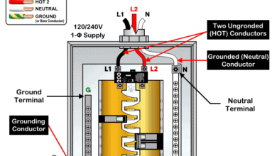
Before wiring, identify the Terminals as follow:
- Line Side (Top): Connects to incoming 3-phase supply (A, B, C).
- Load Side (Bottom): Connects to the outgoing 3-phase load.
Wiring Steps:
- Turn OFF the main breaker and verify no power using a multimeter.
- In the High-Leg Delta panel, locate the three-phase bus bars:
- Left Bus = A-phase (120V to neutral)
- Center Bus = B-phase (High leg, 208V to Neutral)
- Right Bus = C-phase (120V to neutral)
- Snap the 3-pole breaker into place so that it connects across all three bus bars (A, B, and C).
- Connect the load conductors (from NEMA 15-60 receptacle) to the breaker terminals:
- Load 1 → Phase A terminal – Black Color
- Load 2 → Phase B terminal (High leg) – Orange Color
- Load 3 → Phase C terminal – Blue Color
- Connect the equipment grounding conductor (EGC) to the panel ground bus.
- If the load needs a Neutral (for control circuit or 120V component), connect the neutral wire from the panel neutral bus (not used in our case i.e. for NEMA 15-60).
Click image or open in a new tab to enlarge
To wire a 3-phase outlet such as NEMA 15-60 to the 3-pole breaker load side terminals, follow the following steps:
- Connects Phase A (Black) to the X Terminal of outlet
- Connect Phase B (Orange) to the Y Terminal of outlet.
- Connect Phase C (Blue) to the Z Terminal of outlet.
- Connect Ground (Green / Bare) to the G Terminal of outlet.
Since NEMA 15 series is a 3-pole, 4-wire grounding & without neutral, hence, no load neutral is required.
Similarly, the following wiring diagram shows the connection of a NEMA 18-60 receptacle via 3-pole breaker both rated for 120/208Y – three-phase supply. The non-grounding receptacle is supplied through a 3-pole circuit breaker with neutral and no EGC, as shown below.
Click image or open in a new tab to enlarge
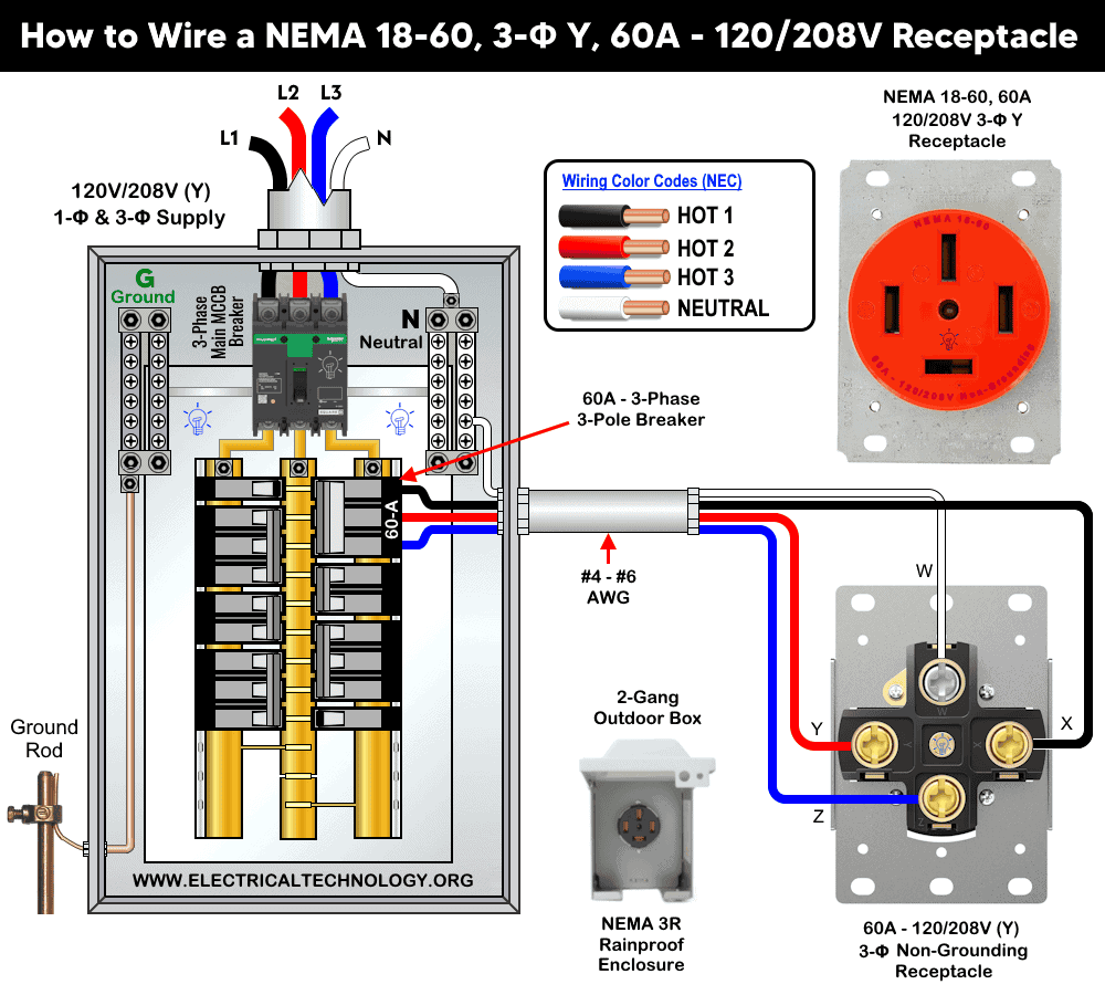
In the example load shown in the fig, we have used to control and wire 60A – (240V and 208Y/120V) receptacles (NEMA 15-60 and NEMA 18-60) with the help of 3-P breaker rated for 60A – 240V and 120/208V Y. For this circuit, we have used #6 AWG copper (THHN) or #4 AWG aluminum (based on 60A and 75 °C rating per NEC Table 310.16, which is the suitable conductor size for 60A circuit and the associated NEMA 15-60R and 18-60R. In addition, use 10 AWG for equipment ground conductor (EGC) per NEC Table 250.122 for a 60A grounding circuits.
Wiring 3-Pole GFCI Breakers
Wiring a 3-pole GFCI breaker is similar to wiring a standard 3-pole breaker, except for the white (built-in pigtail) wire. This pigtail must be connected to the neutral busbar in the main service panel.
In most three-phase circuits, a neutral wire is not required. However, if the circuit does require a neutral, connect the neutral wire from the GFCI breaker directly to the load instead of the neutral busbar. If a neutral connection is not available from the GFCI load terminal, connect it from the neutral busbar to the load point.
The following wiring diagram shows a 20A, 208V, 3-pole, 3-phase GFCI breaker used to protect a 208V three-phase appliance.
Click image or open in a new tab to enlarge

Instructions, Precautions & Codes
- The suitable wire size is 6 AWG copper (or #4 AWG aluminum) to use with a 60A outlet and circuit breaker – NEC Table – 310.16, Table – 210.24(1) and NEC 240.4(D)(4). Therefore, use #12/3 cable (three hot wires and one ground (and one neutral if required) for a 60A-240V 3-P breaker and associated load circuits.
- For a 60A circuit , the equipment grounding conductor (EGC) can be #10 AWG copper. NEC Table 250.122.
- The correct size of breaker is 3-pole, 60A circuit breaker or GFCI for a 60A-240V three-phase outlet – NEC 210.21(B)(2).
- With a 3-pole, 60A breaker, the appropriate cable types include THHN/THWN-2 (Copper, Aluminum or Copper-Clad Aluminum). Use THHN/THWN-2 for indoor (conduit), THWN-2 or XHHW-2 for outdoor or wet locations, or SOOW flexible cord (indoor/outdoor), Type SER or MC cable for feeder cable and Type UF-B or USE-2 for underground feeder.
- A three-pole 60A breaker can be used for 48A continuous load (which lasts 3 or more hours) and maximum 60A non-continuous load – 210.19(A), 210.20(A), 215.2(A), 215.3, and 230.42(A).
- A 3-pole, 60-amp breaker at 240 volt can handle non-continuous load of 14,400 watts (60A × 240V). For continuous use, limit the load to about 11,520 watts (80% of 14,400W).
Resources:
Standard Breakers & GFCI Breakers Wiring Installations
- How to Wire a 1-Pole Breaker
- How to Wire a 2-Pole Breaker
- How to Wire a 3-Phase, 3-Pole Breaker … You Are Here
- How to Wire a Tandem Breaker
- How to Wire a 1-Pole GFCI
- How to Wire a 2-Pole GFCI
- How to Wire a 3-Phase, 3-Pole GFCI Breaker
- How to Wire GFCI Circuit Breakers
- How to Wire an AFCI Breaker
Sizing Breakers, Wires, and Panels
- How to Size a Circuit Breaker?
- How to Size a Breaker and Wires in AWG with EGC for Load?
- How to Find the Proper Size of Wire & Cable In Metric & Imperial Systems
- How to Size a Load Center, Panelboards and Distribution Board?
- How to Determine the Right Size Capacity of a Subpanel?
- How to Find the Right Wire Size for 100A Service 120V/240V Panel?
- How to Size Service-Entrance Conductors and Feeder Cables?
- How to Size Feeder Conductors with Overcurrent Protection
- How to Size a Branch Circuit Conductors with Protection?
- How to Size Equipment Grounding Conductor (EGC)?
- How to Size Grounding Electrode Conductor (GEC)?
- How to Size Motors FLC, HP, Voltage, Breaker Size and Wire Size
- What is the Correct Wire Size for 100A Breaker and Load?
- What is the Right Wire Size for 15A Breaker and Outlet?
- What is the Suitable Wire Size for 20A Breaker and Outlet?
General Outlets and GFCI/AFCI Receptacles Wiring
- How to Wire an Outlet Receptacle? Socket Outlet Wiring Diagrams
- How to wire a GFCI Outlet?
- How to Wire GFCI Combo Switch and Outlet
- How to Wire an AFCI Combo Switch
- How to Wire an AFCI Outlet?
- How to a Wire 3-Way Combination Switch and Grounded Outlet?
- How to Wire Combo Switch and Outlet? – Switch/Outlet Combo Wiring Diagrams
- How to Wire a 15A – 120V Outlet – NEMA 5-15 Receptacle
- How to Wire a 20A – 120V Outlet – NEMA 5-20 Receptacle
- How to Wire a 15A – 240V Outlet – NEMA 6-15 Receptacle
- How to Wire a 20A – 240V Outlet – NEMA 6-20 Receptacle
- How to Wire a 50A – 125/250V Outlet – NEMA 14-50 Receptacle
Switches Wiring
- How to Wire Single Pole, Single Throw (SPST) as 2-Way Switch?
- How to Wire Single Pole, Double Throw (SPDT) as 3-Way Switch?
- How to Wire Double Pole, Single Throw Switch? Wiring DPST
- How to Wire Double Pole, Double Throw Switch? Wiring DPDT
- How to Wire Double Switch? 2-Gang, 1-Way Switch – IEC & NEC
- How to Wire 4-Way Switch (NEC) or Intermediate Switch as 3-Way (IEC)?
- How to Wire Auto & Manual Changeover & Transfer Switch – (1 & 3 Phase)
Finding the Number of Breakers/Outlets in a Circuit
- How to Determine the Number of Circuit Breakers in a Panelboard?
- How to Find the Number of Outlets on a Single Circuit Breaker?
- How to Find Voltage & Ampere Rating of Switch, Plug, Outlet & Receptacle
- How to Calculate the Number of Fluorescent Lamps in a Final Sub Circuit?
- How to Calculate the Number of Incandescent Lamps in a Final Sub Circuit?
- How to Determine the Number of Lighting Branch Circuits?
- How to Determine the Number of Branch Circuits? – 3 Ways
- How to Find the Number of Lights on a Single Circuit Breaker?
Main Panels Wiring Tutorials
- How to Wire 120V/240V Main Panel? Breaker Box Installation
- How to Wire 208V/120V, 1-Phase & 3-Phase Main Panel?
- How to Wire 240V, 208V & 120V, 1 & 3-Phase, High Leg Delta Main Panel?
- How to Wire 277V/480V, 1-Phase & 3-Phase Main Service Panel?
- How to Wire a Subpanel? Main Lug Installation for 120V/240V
- Single Phase Electrical Wiring Installation in Home according to NEC & IEC
- Three Phase Electrical Wiring Installation in Home – NEC & IEC
- How To Wire a Single Phase kWh Meter – 120V/240V
- How to Wire a Three-Phase Meter? 120/208/240/277/347/480/600V
General Wiring Installation Tutorials:
- How to Toggle Electric Water Heater Between 120V and 240V?
- How to Wire 120V Water Heater Thermostat – Non-Simultaneous?
- How to Wire 240V Water Heater Thermostat – Non-Continuous?
- How to Wire 3-Phase Simultaneous Water Heater Thermostat?
- How to Wire Twin Timer for 120V/240V Circuits – ON/OFF Delay
- How to Wire ST01 Timer with Relay & Contactor for 120V/240V Motors?
- How to Wire Multifunction ON/OFF Delay Timer for 120V/240V Motors?
- Even More Residential Wiring Installation Tutorials
Related Posts:
- Difference Between 1-Pole and 2-Pole Breakers – NEC & IEC
- Should GFCI Protection Be in the Main Panel or Receptacle?
- Can you use 15A Breaker on 20A Circuit and Vice Versa?
- Can I Use a 1-Phase Breaker on a 3-Phase Supply & Vice Versa?
- Can I Use a 240V Breaker on a 120V Circuit and Vice Versa?
- Can You use a 15A Outlet on a 20A Circuit and Vice Versa?
- How Does a Standard Breaker Respond to Electrical Fault?
- Why Doesn’t a Standard Breaker Protract Against Ground Faults?
- How Do GFCI and Standard Breakers Respond to Ground Faults?