How to Wire a Single-Pole Circuit Breaker in a 120/240V Panel
How to Install a Standard 1-P, 15A – 120V Breaker for Branch Circuits
Single-Pole Breakers
A single-pole breaker is a circuit breaker designed to control and protect one “hot” wire (phase conductor) in a 120V branch circuit. It is the most common type of breaker used in residential and commercial installations for standard lighting and general-purpose outlet circuits.
1-pole breakers are used to protect small-load appliances operating on 120V circuits in North America (the U.S. and Canada) and some parts of South America. They are connected in branch circuits using one hot wire, a neutral wire, and a ground wire to protect against short circuit and overcurrent.
In residential applications, single-pole breakers (typically rated 15A or 20A) are commonly used for light-duty circuits such as lighting points, ceiling fans, televisions, mobile chargers, and general-purpose outlets and receptacles. In commercial applications, single-pole breakers may also be used for heavier-duty circuits, with ratings ranging from 15A up to 100A or more.
Characteristics:
- Number of Poles: Single-pole: Connects to one line (either L1 or L2), that is, one hot conductor (black or red).
- Voltage: Operates on and protects 120V branch circuits. (Line-to-Neutral).
- Amperage Rating: Commonly used in 15A to 100A+. Standard Rating in NEC Table 240.6(A) is 10A – 6kA.
- Wiring: Only one hot conductor from the breaker, along with the neutral and ground conductors from the neutral and ground busbars, connects to the 120V branch-circuit load.
- Operation: Trips when there is an overload, short circuit, or fault on the single hot (or phase) wire.
- Application: Used for standard lighting, outlets, receptacles, sockets and small appliances.
Wiring a Single-Pole Breaker
If you plan to replace a damaged breaker or install a new single-pole breaker in a 120V/240V main panel, follow the installation guide below.
A standard single-pole breaker connects to one hot wire and one neutral wire. It protects a 120-volt circuit and is rated typically for 15 amps or 20 amps. When a fault occurs (such as overload or short circuit), it automatically trips and disconnects the circuit to prevent damage or fire hazards. It occupies one slot in the electrical panel.
To wire a single-pole breaker in 120V/240V panel, follow the following simple steps.
- Turn Off the Main Power: Locate and turn off the main breaker to cut power to all branch circuits. Use a non-contact voltage tester to verify that no voltage is present.
- Identify the Cable: Use the correct cable for the circuit: Use 12/2 AWG NM-B cable for a 20A breaker
Cable conductors include:
- Black (Hot) – Carries 120V to the load
- White (Neutral) – Returns current from the load
- Bare/Green (Ground) – safety grounding wire (EGC)
- Prepare the Wires
- Strip about ½ inch (≈12 mm) of insulation from each conductor.
- Keep conductors neat and long enough to reach the breaker, neutral, and ground bars.
- Connect the Wires
- Hot Wire (Black): Insert the black wire into the terminal screw of the single-pole breaker. Tighten securely.
- Neutral Wire (White): Connect the white wire to the neutral bar (silver-colored screws).
- Ground Wire (Bare/Green): Connect the ground wire to the ground bar (green screws or shared bar).
Note: In many panels, the neutral and ground bars are bonded (connected together) in the main service panel.
- Install the Breaker: Snap the single-pole breaker firmly into the panel bus bar. It should connect to one hot leg (120V).
- Label the Circuit: Clearly label the new breaker slot, e.g., “Living Room Outlets – 15A / 120V”
- Restore Power and Test: Turn the main breaker back ON. Switch ON the new single-pole breaker.
Test voltage between:
- Hot (black) and Neutral (white) → ~120V
- Hot (black) and Ground (bare/green) → ~120V
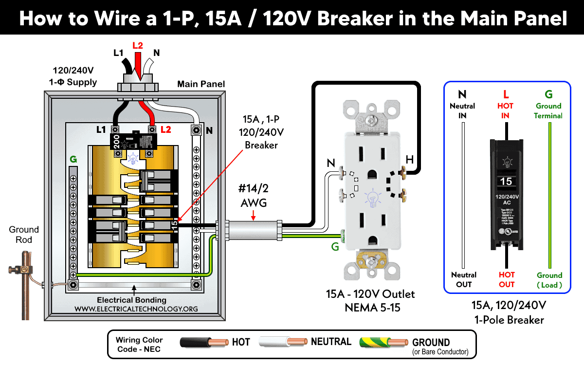
As an example load shown in the fig, we have used to control and wire 15A – 125V receptacle (NEMA 5-15) with the help of 1-P breaker rated for 15A – 120V. For this circuit, we have used #14 AWG copper wire, which is the correct size for a 15A circuit (as per NEC Table 310.16) and the associated NEMA 5-15R outlet. Moreover, Similar wire size i.e. 14AWG should be used for equipment ground conductor (EGC) per NEC Table 250.122.
As mentioned before, 1-pole breakers are used for standard 120V circuits with lower-power devices like lighting fixtures and outlets for small appliances. In other words, single-pole breakers cannot be used in place of two-pole breakers, which are designed for 240V circuits where both poles (i.e., two hot wires, L1 and L2) must be simultaneously controlled and protected. Expect the 15A outlet, the single pole breaker can be wired for different ratings and NEMA outlets used in 120V supply systems such as.
Wiring 1-Pole GFCI Breakers
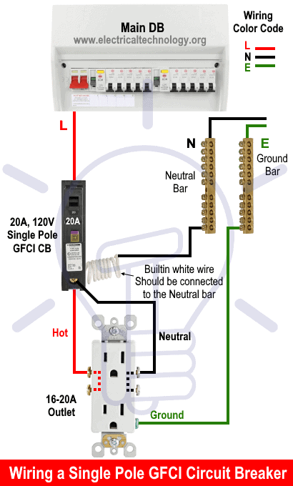
Wiring a 1-pole GFCI breaker is same as wiring ordinary 1-pole breaker except the white (built-in pigtail) wire in the GFCI connects to the neutral busbar in the main panel. Moreover, the Neutral from the GFCI is directly connects to the load point instead of wiring it from the neutral busbar.
The following wiring diagram shows a 15A, 120V standard outlet wired and protected by a 1-pole GFCI breaker rated for 15A – 120V.
Click image or open in a new tab to enlarge
Similarly, the given wiring diagrams shows the installation of 1-Pole GFI breakers with 20A outlets and TT-30 outlet etc. In addition, the different wiring diagrams shows the installation of 1-Pole breakers with 15A, 20A and 30A GFCI outlets.
Instructions, Precautions & Codes
- The suitable wire size is 14 AWG copper (or #12 AWG aluminum) to use with a 15A outlet and circuit breaker – NEC Table – 310.16, Table – 210.24(1) and NEC 240.4(D)(4). Therefore, use #14/2 cable (hot wire, a neutral and one ground) for a 15A-120V breaker and associated load circuits.
- For a 15A circuit , the equipment grounding conductor (EGC) can be #14 AWG copper. NEC Table 250.122.
- The correct size of breaker is 1-pole, 15A circuit breaker or GFCI for a 15A-120V outlet – NEC 210.21(B)(2).
- With a 1-pole, 15A breaker, the appropriate cable types include NM-B (Romex) for indoor and dry locations, UF-B for outdoor or underground runs, and THHN/THWN conductors when installed in conduit.
- A single-pole 15A breaker can be used for 12A continuous load (which lasts 3 or more hours) and maximum 15A non-continuous load – 210.19(A), 210.20(A), 215.2(A), 215.3, and 230.42(A).
- A 1-pole, 15-amp breaker at 120 volt can handle non-continuous load of 1,800 watts (15A × 120V). For continuous use, limit the load to about 1,440 watts (80% of 1,800W).
- Do not use 20A outlet on 15A circuit breaker. If more than one receptacle on the same circuit, you may allowed to use 15A outlet on 20A circuit breaker. In short, It is code to use 15A outlet on 20A breaker (NEC 210.21(B)(2)), but it is not allowed to use 20A outlet on 15A breaker.
Resources:
Standard Breakers & GFCI Breakers Wiring Installations
- How to Wire a 1-Pole Breaker… You Are Here
- How to Wire a 2-Pole Breaker
- How to Wire a 3-Phase, 3-Pole Breaker
- How to Wire a Tandem Breaker
- How to Wire a 1-Pole GFCI
- How to Wire a 2-Pole GFCI
- How to Wire a 3-Phase, 3-Pole GFCI Breaker
- How to Wire GFCI Circuit Breakers
- How to Wire an AFCI Breaker
Sizing Breakers, Wires, and Panels
- How to Size a Circuit Breaker?
- How to Size a Breaker and Wires in AWG with EGC for Load?
- How to Find the Proper Size of Wire & Cable In Metric & Imperial Systems
- How to Size a Load Center, Panelboards and Distribution Board?
- How to Determine the Right Size Capacity of a Subpanel?
- How to Find the Right Wire Size for 100A Service 120V/240V Panel?
- How to Size Service-Entrance Conductors and Feeder Cables?
- How to Size Feeder Conductors with Overcurrent Protection
- How to Size a Branch Circuit Conductors with Protection?
- How to Size Equipment Grounding Conductor (EGC)?
- How to Size Grounding Electrode Conductor (GEC)?
- How to Size Motors FLC, HP, Voltage, Breaker Size and Wire Size
- What is the Correct Wire Size for 100A Breaker and Load?
- What is the Right Wire Size for 15A Breaker and Outlet?
- What is the Suitable Wire Size for 20A Breaker and Outlet?
General Outlets and GFCI/AFCI Receptacles Wiring
- How to Wire an Outlet Receptacle? Socket Outlet Wiring Diagrams
- How to wire a GFCI Outlet?
- How to Wire GFCI Combo Switch and Outlet
- How to Wire an AFCI Combo Switch
- How to Wire an AFCI Outlet?
- How to a Wire 3-Way Combination Switch and Grounded Outlet?
- How to Wire Combo Switch and Outlet? – Switch/Outlet Combo Wiring Diagrams
- How to Wire a 15A – 120V Outlet – NEMA 5-15 Receptacle
- How to Wire a 20A – 120V Outlet – NEMA 5-20 Receptacle
- How to Wire a 15A – 240V Outlet – NEMA 6-15 Receptacle
- How to Wire a 20A – 240V Outlet – NEMA 6-20 Receptacle
- How to Wire a 50A – 125/250V Outlet – NEMA 14-50 Receptacle
Switches Wiring
- How to Wire Single Pole, Single Throw (SPST) as 2-Way Switch?
- How to Wire Single Pole, Double Throw (SPDT) as 3-Way Switch?
- How to Wire Double Pole, Single Throw Switch? Wiring DPST
- How to Wire Double Pole, Double Throw Switch? Wiring DPDT
- How to Wire Double Switch? 2-Gang, 1-Way Switch – IEC & NEC
- How to Wire 4-Way Switch (NEC) or Intermediate Switch as 3-Way (IEC)?
- How to Wire Auto & Manual Changeover & Transfer Switch – (1 & 3 Phase)
Finding the Number of Breakers/Outlets in a Circuit
- How to Determine the Number of Circuit Breakers in a Panelboard?
- How to Find the Number of Outlets on a Single Circuit Breaker?
- How to Find Voltage & Ampere Rating of Switch, Plug, Outlet & Receptacle
- How to Calculate the Number of Fluorescent Lamps in a Final Sub Circuit?
- How to Calculate the Number of Incandescent Lamps in a Final Sub Circuit?
- How to Determine the Number of Lighting Branch Circuits?
- How to Determine the Number of Branch Circuits? – 3 Ways
- How to Find the Number of Lights on a Single Circuit Breaker?
Main Panels Wiring Tutorials
- How to Wire 120V/240V Main Panel? Breaker Box Installation
- How to Wire 208V/120V, 1-Phase & 3-Phase Main Panel?
- How to Wire 240V, 208V & 120V, 1 & 3-Phase, High Leg Delta Main Panel?
- How to Wire 277V/480V, 1-Phase & 3-Phase Main Service Panel?
- How to Wire a Subpanel? Main Lug Installation for 120V/240V
- Single Phase Electrical Wiring Installation in Home according to NEC & IEC
- Three Phase Electrical Wiring Installation in Home – NEC & IEC
- How To Wire a Single Phase kWh Meter – 120V/240V
- How to Wire a Three-Phase Meter? 120/208/240/277/347/480/600V
General Wiring Installation Tutorials:
- How to Toggle Electric Water Heater Between 120V and 240V?
- How to Wire 120V Water Heater Thermostat – Non-Simultaneous?
- How to Wire 240V Water Heater Thermostat – Non-Continuous?
- How to Wire 3-Phase Simultaneous Water Heater Thermostat?
- How to Wire Twin Timer for 120V/240V Circuits – ON/OFF Delay
- How to Wire ST01 Timer with Relay & Contactor for 120V/240V Motors?
- How to Wire Multifunction ON/OFF Delay Timer for 120V/240V Motors?
- Even More Residential Wiring Installation Tutorials
Related Posts:
- Difference Between 1-Pole and 2-Pole Breakers – NEC & IEC
- Should GFCI Protection Be in the Main Panel or Receptacle?
- Can you use 15A Breaker on 20A Circuit and Vice Versa?
- Can I Use a 1-Phase Breaker on a 3-Phase Supply & Vice Versa?
- Can I Use a 240V Breaker on a 120V Circuit and Vice Versa?
- Can You use a 15A Outlet on a 20A Circuit and Vice Versa?
- How Does a Standard Breaker Respond to Electrical Fault?
- Why Doesn’t a Standard Breaker Protract Against Ground Faults?
- How Do GFCI and Standard Breakers Respond to Ground Faults?


