How to Wire Auto & Manual Changeover & Transfer Switch – (1 & 3 Phase)
Manual and Automatic Transfer and Changeover Switch Wiring & Connection
In our step by step electrical wiring installation tutorials series, We will show how to wire and connect single phase and three phase automatic and manual changeover and transfer switches to the home distribution board and main panel to use the backup power supply such us batteries power with UPS and inverters or generator power in case of emergency breakdown and power outage. The wiring diagrams show both the 120V/240V NEC and 230V/400V IEC system voltages (single phase and three phase supply) for manual and auto transfer and changeover switches. Now let’s begin as follows.
Related Posts:
- How to Connect a Portable Generator to the Home Supply – 4 Methods
- Manual & Auto UPS / Inverter Wiring Diagram using ATS & Changeover Switch
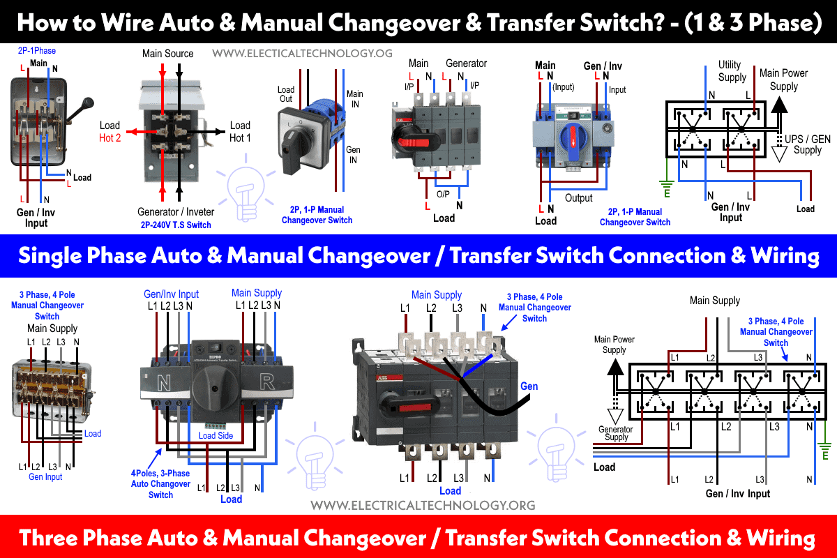
The following fig-1 shows the different 1-Phase and 3-Phase connections for manual and automatic changeover and transfer switches. Lets explain one by one in detail as follows.
Click image to enlarge
How to Wire Single Phase Manual Transfer / Changeover Switch?
Wiring 230V, 1-Phase Changeover Switch – IEC
In fig-2, different connection and wiring diagrams are shown for a two pole, single phase manual changeover switch. The upper portion of the changeover switch is directly connected to the main power supply while the lower first and right connections slots are connected to the backup power supply like generator or inverter. The left side of lower slots are connected to the main board as load.
In case of power failure, the manual changeover switch can be changed to the generator / inverter position. This way, power supply will continue to the load points through the inverter or generator. When power supply restores from the power house, simply switch back the changeover switch position to the “Main Power Supply”.
Click image to enlarge

Related Posts:
- Single Phase Electrical Wiring Installation in Home – NEC & IEC
- Three Phase Electrical Wiring Installation in Home – NEC & IEC
Wiring 120V & 240, 1-Phase Manual Transfer Switch – NEC
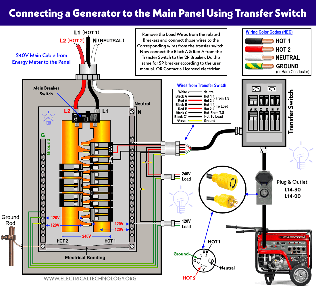
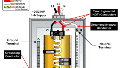
The following wiring diagram in fig-3 shows the Reliance manual transfer switch connected to the main 120/240 V panel and a portable generator. Step by step guide is posted before in the post under the title Wiring a Portable Generator Using Manual Transfer Switch for 120 & 240V.
Click image to enlarge
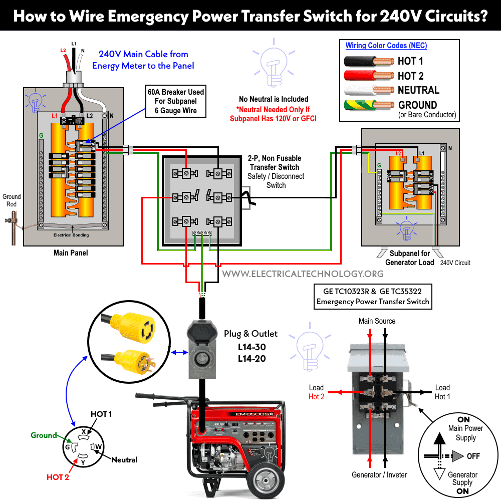
The related wiring diagram in fig-4 shows the 2 pole manual transfer switch (GE TC10323R / GE TC35322) connected to the main 120/240 V panel and a portable generator to 240V subpanel installed for emergency power. Step by step guide is posted before in the post under the title Wiring a Generator Using Manual Transfer Switch for 240V.
Click image to enlarge
Related Posts:
- How to Wire 120V & 240V Main Panel? Breaker Box Installation
- How to Wire 208V & 120V, 1-Phase & 3-Phase Main Panel?
How to Connect Single Phase Automatic Changeover / Transfer Switch (ATS)
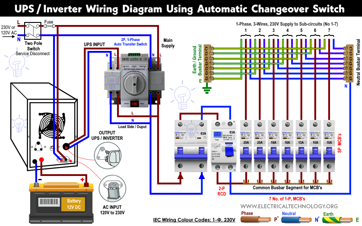
If you are tired of manual operation of changeover switches, ATS is the best alternative to use then. In the following fig-5, the backup power of batteries is connected to the main distribution board through 2-Pole, single phase automatic changeover or transfer switch (ATS) and UPS / Inverter.
The working and operation of this circuit is the same as above except the automatic changeover switch (ATS) will detect the utility power when restored from the power house and automatically transfer from the Generator / Inverter to the Main Power supply. In case when utility power is not available, the ATS will transfer the switching position to the Inverter, hence electrical appliances will be still in operation mode without interruption through the stored power in the batteries.
Click image to enlarge
Related Posts:
- How to Wire Single-Phase, 230V Consumer Unit with RCD? IEC, UK & EU
- How to Wire a Garage Consumer Unit?
How to Wire Three Phase Manual Changeover/Transfer Switch
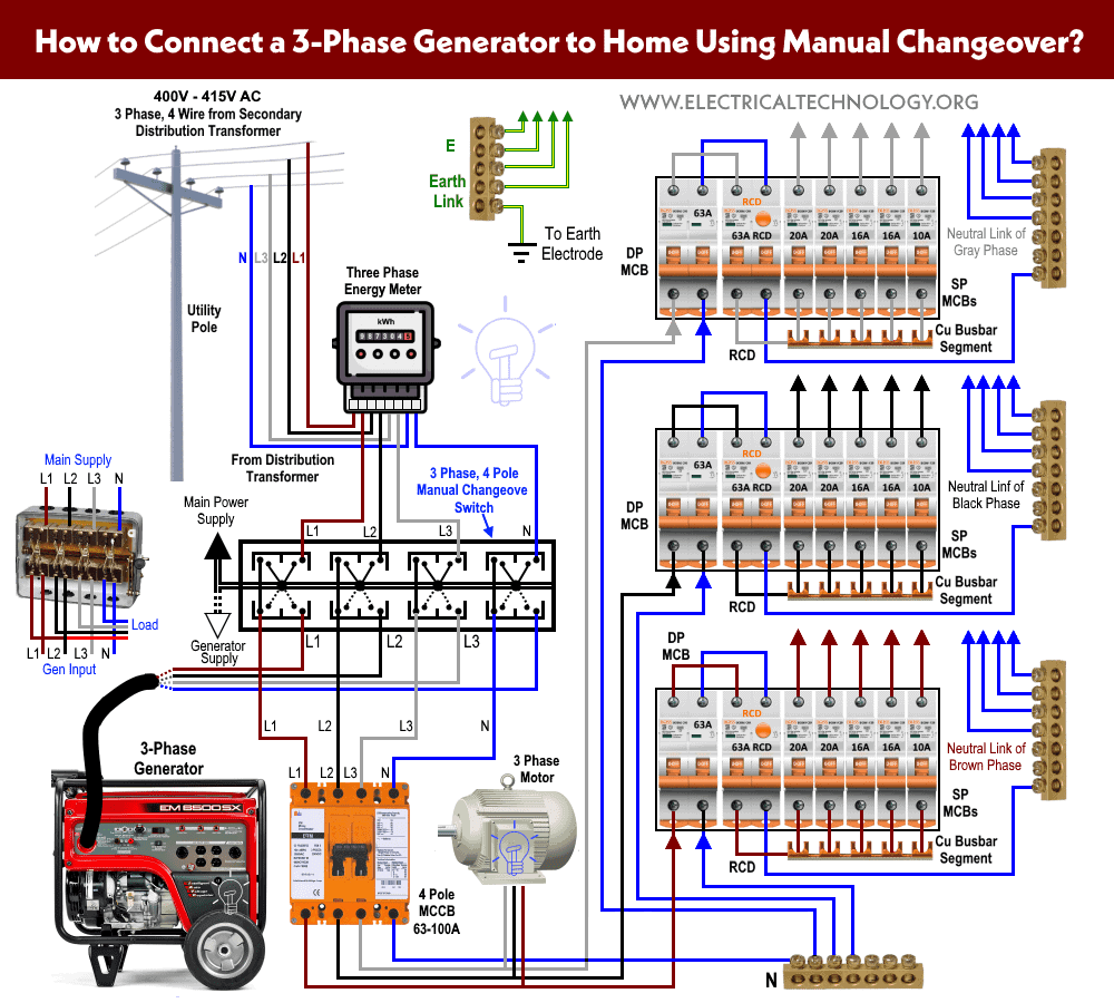
Fig-6 shows how to wire a four pole, three phase manual changeover switch to the main distribution board. This is the same connection as we discussed above for single phase wiring except that there are three phase wires instead of line and neutral.
The three phase utility power (L1, L2, L3 & N) are directly connected to the upper side of the manual changeover switch, while the backup power of the three phase generator is connected to the first four (right) slots of the lower side. The left side four slots connection points are connected to the load then.
Since the operation is manual, You have to change the changeover lever to the appropriate position manually to restore the power i.e. Change the lever position to the “Generator Supply” when main power is not available and then back to the “Main Power” when utility power is restored.
Click image to enlarge
Related Posts:
- A Complete Guide About Solar Panel Installation. Step by Step Procedure with Calculation & Diagrams
- How to Wire Batteries in Series, Parallel and Series-Parallel?
- Series, Parallel and Series-Parallel Connection of Solar Panels
How to Install a Three Phase Automatic Transfer/Changeover Switch
Fig-7 shows 4-Poles, 3-Phase automatic transfer switch (ATS) connection to the main distribution board. All the wiring connections are the same as above for manual operation of three phase changeover switch but the switching operation is automatic.
In case of emergency breakdown, the automatic transfer switch will automatically divert the switching position to the “Generator Supply” and when the main supply restores, it will transfer the power flow to the “Utility Power” when using emergency generator set for backup power.
Click image to enlarge

Related Posts:
How to Connect a Generator using ATS / Changeover Switch
In our previous post, we have shown in very details that how to connect a portable generator to the home supply using automatic and manual transfer/changeover switches. It also shows the working and operation for different changeover switches wiring connections like, single phase manual changeover switch to the generator, three phase manual transfer switch connection to the generator as well as single phase and three phase automatic transfer switches connections to the 1 and 3 phase generators and main distribution board/consumer unit and main panel and load centers.
How to Wire UPS / Inverter with Transfer Switch / Changeover Switch
In our another wiring tutorial, we have discussed in detail about How to do Manual & Auto UPS / Inverter Wiring using Changeover / ATS Switch?. You will be able to know how to connect UPS / Inverters and batteries to the home supply with the help of two poles, single phase automatic and manual changeover / Transfer switch in case of partial load and full load as well as how the system works at all?
Note: Use 6 AWG (7/064″ or 16mm2) cable and wire size to connect the UPS to the main panel board.
Related Posts:
- Basic Components Needed for Solar Panel System Installation
- How to Wire Solar Panel to 120-230V AC Load and Inverter?
Wiring Color Code (IEC & NEC):
We have used the IEC and IEC wiring color codes for 230V/400V and 120V/240V circuits. You may use the local area codes or i IEC – International Electrotechnical Commission (UK, EU etc.) or NEC (National Electrical Code [US & Canada] where;
NEC:
Single Phase 120V AC:
- Black = Hot or Line
- White = Neutral
- Green / Yellow or bare conductor = Ground Wire
Single Phase 240V AC:
- Black = Hot 1 or Line 1
- Red = Hot 2 or Line 2
- White = Neutral
- Green / Yellow or bare conductor = Ground Wire
Three Phase 208 AC:
- Black = Hot 1 or Line 1
- Red = Hot 2 or Line 2
- Blue = Hot 3 or Line 3
- White or Gray = Neutral
- Green / Yellow or bare conductor = Ground Wire
Three Phase 240 AC (High Leg Delta):
- Blue = Hot 1 or Line 1
- Orange = Hot 2 or Line 2 (HIGH LEG DELTA)
- Black = Hot 3 or Line 3
- White or Gray = Neutral
- Green / Yellow or bare conductor = Ground Wire
Three Phase 480V & 600V AC
- Brown = Hot 1 or Line 1
- Orange = Hot 2 or Line 2
- Yellow = Hot 3 or Line 3
- White or Gray = Neutral
- Green / Yellow or bare conductor = Ground Wire
IEC:
Single Phase 230V AC:
- Brown = Phase or Line
- Blue = Neutral
- Green / Yellow = Earth Conductor = Earth Conductor
Three Phase 400V – 415V AC:
- Brown = Phase 1 or Line 1
- Black = Phase 2 or Line 2
- Grey = Phase 3 or Line 3
- Blue = Neutral
- Green / Yellow = Earth Conductor
Related Posts:
General Precaution
If you are still facing difficulties to wire the UPS and batteries or portable generator using changeover and ATS switches, please leave a comment in the comment box below and we will be there to assist you more in details.
Related Electrical Wiring Installation Tutorials.
- How to Wire a Single Element Water Heater and Thermostat?
- How to Wire 120V Water Heater Thermostat – Non-Simultaneous?
- How to Wire 120V Simultaneous Water Heater Thermostat?
- How to Wire 240V Water Heater Thermostat – Non-Continuous?
- How to Wire 240V Simultaneous Water Heater Thermostat?
- How to Wire 3-Phase Simultaneous Water Heater Thermostat?
- How to Wire 3-Phase Non-Simultaneous Water Heater Thermostat?
- How to Toggle Electric Water Heater Between 120V and 240V?
- Staircase Wiring Circuit Diagram – How to Control a Lamp from 2 Places?
- Corridor Wiring Circuit Diagram – Hallway Wiring using 2-Way Switches
- Tunnel Wiring Circuit Diagram for Light Control using Switches
- Hospital Wiring Circuit for Light Control using Switches
- Hotel Wiring Circuit – Bell Indicator Circuit for Hotelling
- Hostel Wiring Circuit Diagram and Working
- Godown Wiring Diagram – Tunnel Wiring Circuit and Working
- Automatic UPS system wiring circuit diagram for Home or Office
- Manual UPS Wiring Diagram With Change Over Switch System.
- How to Wire 4-Way Switch (NEC) or Intermediate Switch as 3-Way (IEC)?
- How to Wire Single Pole, Single Throw (SPST) as 2-Way Switch?
- How to Wire Single Pole, Double Throw (SPDT) as 3-Way Switch?
- How to Wire Double Pole, Single Throw Switch? Wiring DPST
- How to Wire Double Pole, Double Throw Switch? Wiring DPDT
- How to Wire Double Switch? 2-Gang, 1-Way Switch – IEC & NEC
- How to a Wire 3-Way Combination Switch and Grounded Outlet?
- How to a Wire Double 3-Way Combination Switch Device?
- Even More Residential Wiring Installation Tutorials


nice job
Nice one
Please send a full supplement on electricity
circuits automatic change over switch,3phase and drawings
thanks
please,send me the circult of automatic change over switch and drawings
thanks
thanks so much for correct and summarised information
Good job u should be a lecturer.pls send d diagram of d automatics changeover in my mailbox and always update me
Hello kindly send me a complete wiring diagram of both both automatic ana manual changeovers in 1 single phase and 3 phase and how you signal them
Hi Amos share too the manuals and diagrams if you get them ndanaduncan@gmail.com
Please.
Hello how are you thank you for skills but please show me circuit diagram of automatic changeover
Thank u
I kindly ask if someone to explain to me how to install a single phase submasible pump and a float switch in tank that has been erected on the ground. I have the following;
1. pump
2. float switch/water level contral switch
3. contral box with a top plan
4. 13A socket
thanks so much and continue with such spirit,,,have learned a lot through you
I’ve been an electrician since 1976 and back then we were inspired by relatives and friends working the craft but today is so much different for our technicians. Knowing and understanding about basic electronics is just important for electricians to work their craft to be successful and productive. This craft will never go away and will only be better.
please l would be very helpful if you could send me a voice video to help learn more.thanks.
Thanks so much for the great work you have done in providing us technological studies
Hi got a very productive sources from you guys..mine is to say thanks alot..still would like to know how to install a three phase automatic change over switch please
Hi there,
Here is the basic wiring diagram for three phase automatic changeover switch.
please send me the manual and automatic changeover switch wiring diagram…video instruction will be of more help
That’s what I was searching for changeover switches installation. Thanks man as it saved my time.
we have 59 electronic changeover switches to 59 flats, which are failing every time there is power failure. Want to know if we can install one single ATS and still be able to calculate each flat’s consumption
Excellent WIRING guide! Proper integration of an Automatic Transfer Switch (ATS) with a UPS or inverter.