How to Wire 1-Phase & 3-Phase Split Load Distribution Board?
Wiring a 230V/400V, 1-Φ & 3-Φ Split Load Distribution Board: UK & EU – IEC
Split Load & Dual Split Load Distribution Boards
The dual split load three phase distribution board is used to supply the electric power supply via main switch and separate RCD/RCCB for each section. This way, the same distribution board can be used to split the load points via multiple RCD’s. In addition, Some of the RCD’s can be used for three phase 400V circuits in commercial and industrial applications while the other RCD’s can be wired for single phase 230V appliances and residential applications.
For example, the three/four poles main switch controls both the 4-poles RCD’s while RCD#1 controls the single or three phase load circuits in separate sections (e.g. load points in the downstairs or story 1, first floor etc.) while RCD#2 controls and protects the single/three phase load circuits in the other part of the residential area (e.g. circuits in the upstairs, second floor or story 2 etc.)
The dual split load or simple split load distribution boards provide high integrity protection having multiple advantages. For example, If first RCD trips because of fault, the whole building will not suffer with immediate darkness i.e. the rest of the circuits will work fine as other RCDs are not depended on the first one. In case of single RCD with fault, the whole area will face a complete power breakdown.
Good to know: A three phase distribution board can be used to provide single phase supply while the single phase consumer unit won’t be able to feed up three phase power circuits.
A distribution board (aka main breaker box, electric panel or panel board) is a combination unit of protective devices (such as main switch, MCB, MCCB, RCD, RCBO, Isolator, fuses and switches etc.) used in commercial (as industrial) and domestic (as residential) applications to safely control and provide electric power supply to the load circuits and appliances.
We will never repeat again and again as we discussed the difference between single phase and three phase power supply as well as balanced and unbalanced loads system in the previous posts and wiring tutorials. For basic revision, following are the common residential and commercial voltage levels in the United Kingdom, Europe and other countries that follow the IEC rules such as UAE, KSA, India, Pakistan, South Africa, Philippine etc.
Related Posts:
- How to Wire a Three Phase, 400V Distribution Board? IEC & UK
- How to Wire Combo of 3 & 1-Φ, 400V/230V Distribution Board?
Single Phase & Three Phase Voltage in UK & EU
Following is the typical power supply distribution system for both single phase and three phase supply voltage in the UK, EU and other countries which follows IEC and UK standards.
- The power transformer is connected to 33kV which step-down the 33kV to 11kV.
- The secondary of the 33kV/11kV transformer is connected to the primary side (which is wired in Delta connection) of the distribution transformer mounted on the utility pole.
- The secondary of the distribution transformer is wired in Star connection.
- The secondary transformer step-down the 11kV voltage in 400V three phase and 230V single phase.
- In the distribution transformer, there are 4 Wires (Three Lines + Neutral) coming out from the star connected secondary side.
- The voltage level between three lines is three phase 400V while the supply voltage between any phase and neutral wire is 230V single phase.
- All the four wires (Three Lines + Neutral) from the secondary side of the transformer are connected to the three phase kWh energy meter and finally entered to the main distribution board for further power supply distribution.
Three Phase Voltage in EU & UK – IEC
3-Φ, 400V (Three Lines + Neutral + Earth)
Where:
- L1 = Line 1 or Phase 1
- L2 = Line 2 or Phase 2
- L3 = Line 3 or Phase 3
- N = Neutral
- E = Earth
In short, 3-Phase, 400V can be achieved by three lines (L1, L2, L2). Keep in mind that Neutral is not always necessary in the three phase wiring systems. Please check the previous wiring diagrams for more details. In addition, Almost all the metallic bodies of the appliances must be connected to the Earth/Ground wire to single or multiple points via earth continuity conductor to the earth plate buried in the soil. (for more details, check the previous post: Electrical Earthing – Methods and Types of Earthing & Grounding
Single Phase Voltage in EU & UK – IEC
1-Φ, 230V (Phase + Neutral + Earth)
Where:
- P = Line 1 or Phase
- N = Neutral
- E = Earth
The single phase load points can be connected through Phase or any line (L1, L2 or L3) and a Neutral wire with protective earth. This way, three wires can be used to connect the single phase load circuits to the 230V power supply.
Please note that we have multiple wiring configuration for three phase split load distribution board i.e.
- Split Load, Single Phase from Three Phase
- Split Load, Three Phase
- Split Load, Three Phase & Single Phase (Combo of 1-Φ & 3-Φ Split Load Distribution Board)
Related Posts:
- How to Wire 1-Phase Split Load Consumer Unit? – RCD+RCBO
- How to Wire 230V Dual Split Load Consumer Unit? – RCD+MCB
How to Wire a 1-Φ Load in a Split Load Distribution Board?
In the following dual split load distribution wiring diagram, there are a total 24 numbers of 1-P MCB’s are wired for single phase 230V load circuits i.e. ceiling fan, air-conditioner, and lighting points etc. via three wires (Phase, Neutral & Earth). You may use RCBO’s or two poles MCB’s based on the system requirements if needed.
The whole circuit is divided in two parts i.e. the 12 Nos of 1-Poles MCB’s (upper portion) are controlled and protected by first RCD (left side) and the rest 12 No. of MCBs (lower portion) are wired to the second RCD (right side). Both the RCD’s are protected and controlled by the 3 or 4 Poles MCB/MCCB main switch as an isolator.
Keep in mind that there are separate Neutral busbars for each section protected by a single RCD. In addition, a common Earth busbar neutral can be used for both RCBO’s and load points connected to the 1-P, MCB circuit breakers.
Click image to enlarge

Related Posts:
- Single Phase Electrical Wiring Installation in Home – NEC & IEC
- Three Phase Electrical Wiring Installation in Home – NEC & IEC
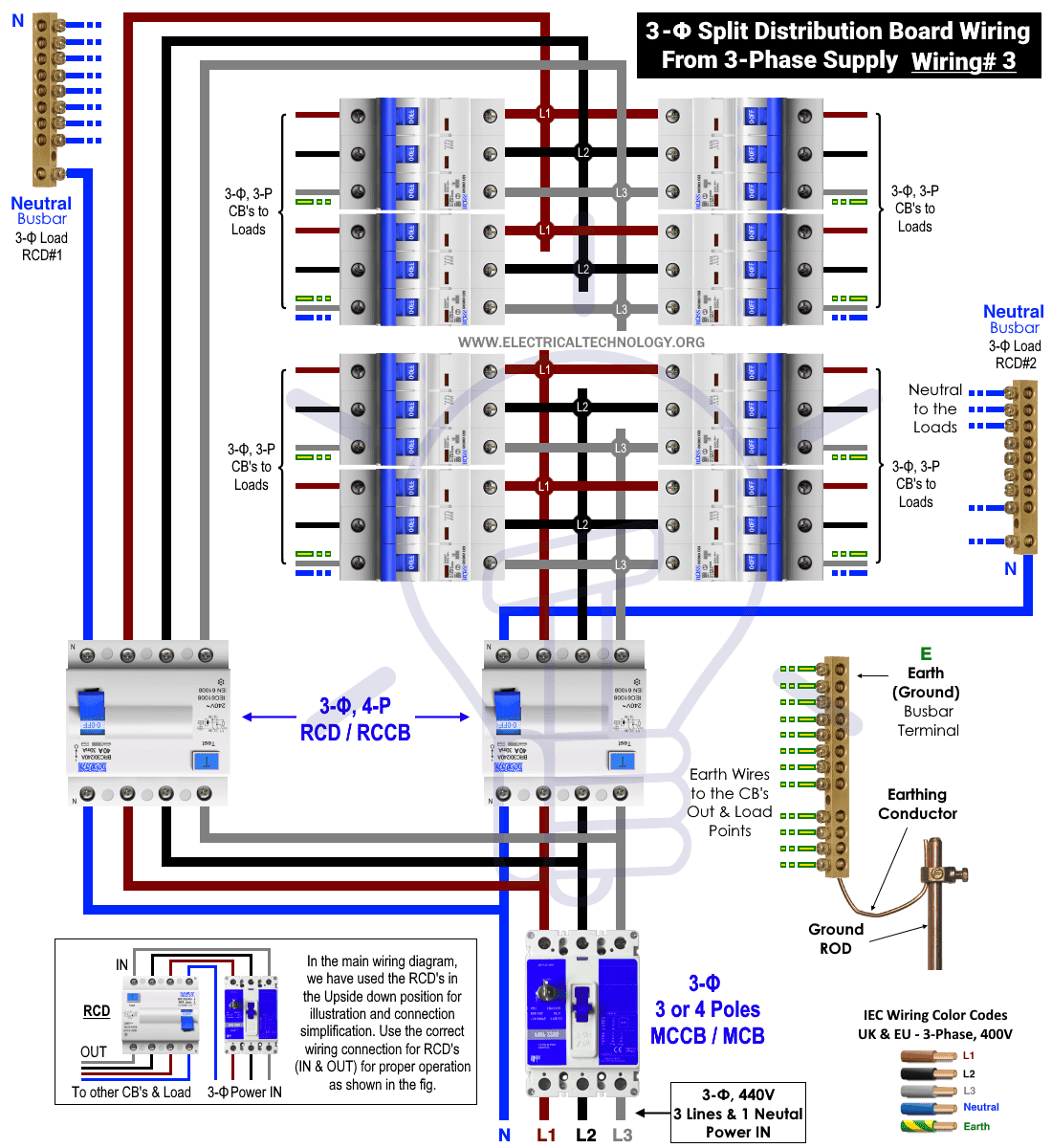
How to Wire a 3-Φ Load in a Split Load Distribution Board?
In this wiring diagram, only three phase load circuits and MCB’s are wired for three phase, 400V load circuits e.g. motors, industrial power sockets/plug, instant water heaters etc. via four or five wires ( 3-Lines + Neutral (optional) + Earth wire).
This is the wiring diagram as above instead showing wiring for 3-phase load circuits. This way, two RCD’s are used to split the load i.e. first RCD controls and protects the three phase load points connected to the upper 3-poles MCB’s Bank. Similarly, the second RCD protects the three phase power circuits connected to the lower 3-P MCB’s Bank.
Click image to enlarge
Related Posts:
- Single-Phase Electrical Wiring installation in a Multi-Story Building
- 3-Phase & 1-Phase Electrical Distribution Wiring Installation in Multistory Building
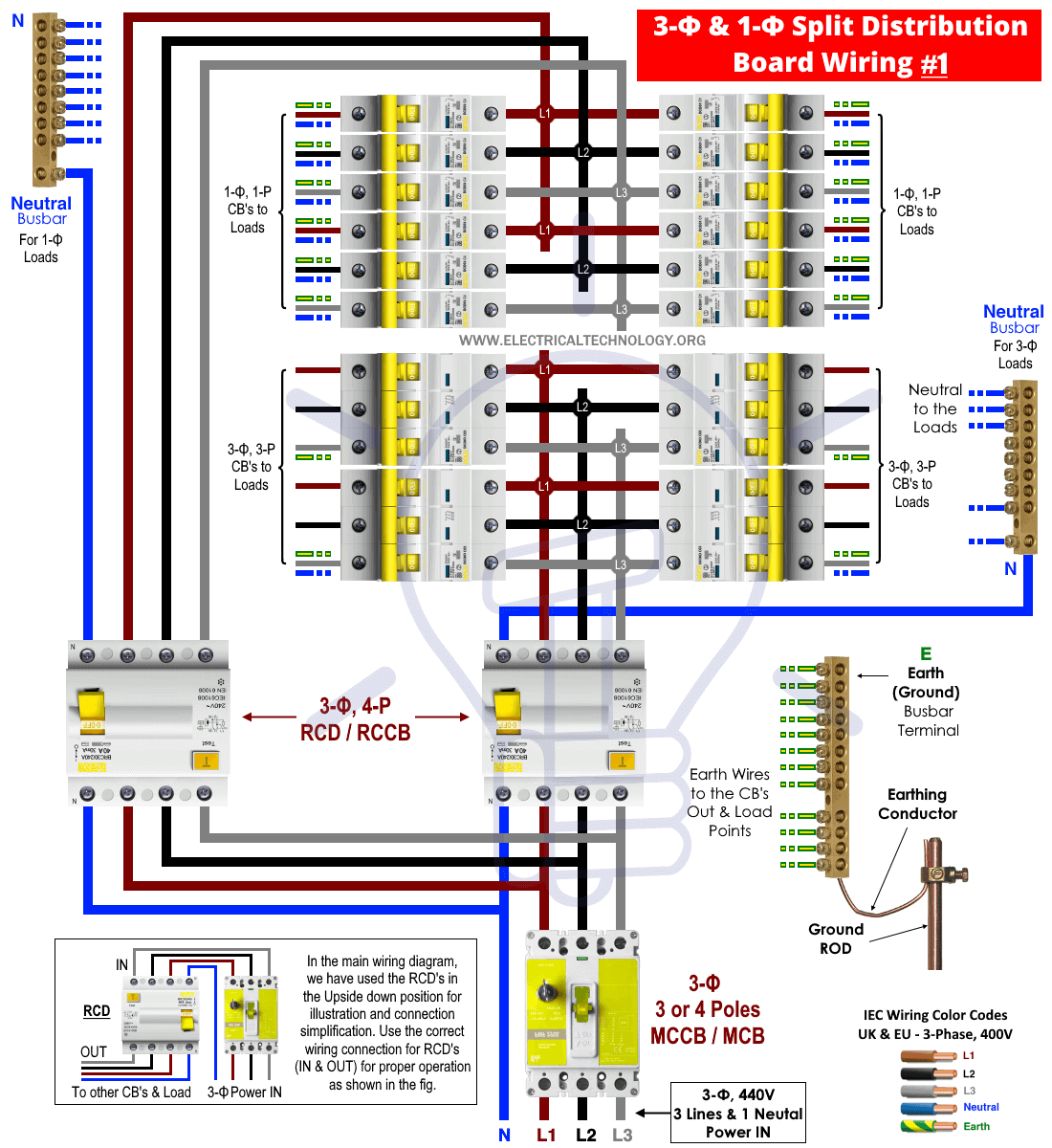
How to Wire Both 1-Φ & 3-Φ Load in a Split Load Distribution Board?
The following wiring diagram shows the combination of both single phase 230V and three phase 400V, split load distribution board. Single phase load circuits i.e. fan, light bulb and other residential devices can be directly connected to the phase, neutral and ground/earth wire.
The first RCD (left side) is used to control and protect the single phase 230V load points connected to single poles MCB’s (12 No of circuit breakers in the upper breaker bank). The second RCD (right side) is wired to protect and control the three phase 400V and load and power circuits connected to three poles MCB’s (4 No of MCB in the lower breaker bank).
The three phase load points i.e. motors, water heaters and power circuits can be directly connected to the three lines + earth wire where Neutral is optional and depends on the design of machine and appliance.
Click image to enlarge
Related Posts:
- How to Wire 240V, 208V & 120V, 1 & 3-Phase, High Leg Delta Main Panel?
- How to Wire 277V & 480V, 1-Phase & 3-Phase, Commercial Main Service Panel?
3-Phase & 1-Phase Split Load Distribution Board Wiring – Old UK Wiring Color Codes
As most of other countries like KSA, UAE, IND, Pak etc. also follow the same level of voltages for both single phase and three phase as IEC but some of them still use the old United Kingdom Wiring color codes (prior 2004). Moreover, we get queries from readership to include the wiring diagrams in RYB wiring colors codes. So here is the wiring of a split load distribution board for 1-Φ & 3-Φ circuits and CB’s according to the old UK wiring color codes.
Click image to enlarge

Related Posts:
- How to Wire 120V & 240V Main Panel? Breaker Box Installation
- How to Wire 208V & 120V, 1-Phase & 3-Phase Main Panel?
Wiring 3-Φ, 400V & 1-Φ 230V Load Circuits in Split Load Distribution Board
In a three phase split load distribution board, two RCD’s are used to protect and control single phase breakers and associated load points and three phase MCBs and connected load circuits. As shown in the below wiring diagram, we have used two RCD’s, i.e. the first one for 400V circuits and the second one for 230V circuits.
You may follow the same diagram i.e. both RCD’s for two different three phase load circuits OR both single phase circuits or a combination of single phase and three phase 400V/230V load circuits.
This way, a single phase load can be directly connected to any Phase (L1, L2 or L3), Neutral and earth wire i.e. three wires. On the other hand, three phase loads can be connected to all three phases (L1, L2 & L3), Ground and Neutral (if needed).
In the following fig for split load distribution board wiring, the protection and control to the single phase and three phase load circuits are as follows.
Single Phase 230V Loads Protected by RCD#2
- Standard Socket via 1-Pole MCB
- Washing Machine via 1-Pole RCBO
Three Phase 400V Loads Protected by RCD#1
- 3-Phase Motor via Three Poles MCB (Three Wires)
- Industrial Power Socket (Five Wires i.e. Three Phases, 1 Neutral & 1 Earth)
Click image to enlarge

Related Posts:
- How to Wire Single-Phase, 230V Consumer Unit with RCD? IEC, UK & EU
- How to Wire Automatic UPS / Inverter to the Home Supply System?
IEC Wiring Color Codes: 400V, 3-Φ: UK & EU
IEC Wiring Color Codes for 400V, 3-Phase, 4-Wire System IEC Wiring Color Codes for 230V, 1-Phase, 2-Wire System The Old UK wiring color codes for single phase and three phase wiring. 400V Three Phase 230V Single Phase
Related Posts:
Instruction & Safety Precautions
- Disconnect the power supply (and make sure it is really swathed OFF) before servicing, repairing or installing electrical equipment. To do so, switch off the main switch in the main consumer unit or distribution board.
- Never stand or touch wet and metal parts while repairing or installation.
- Read carefully all the cautions and instructions and follow them strictly while doing this tutorial or any other work in practical related to electrical works.
- Always, use the right size cable and wire, proper size outlets and switch and suitable size of circuit breakers. You may also use the Wire and Cable size calculator to find the right gauge size.
- Never ever try to play with electricity (as it is dangerous and can be fatal) without proper guidance and care. Do the installation and repairing work in presence of experienced persons having vast knowledge and good practice who knows how to deal with electricity.
- Doing your own electrical work is dangerous as well as illegal in some cases. Contact the licensed electrician or the electric power supply provider before practicing any change/modification in electrical wiring connections.
- The distribution board should not be installed 2.2 meter above the floor, must be protected from the corrosion and away from watery areas. All the wires should be covered in the panel board (i.e. it should not hang outside the panel). Finally, there must be a safety sign near the distribution board.
- The author will not be liable for any losses, injuries, or damages from the display or use of this information or if you try any circuit in wrong format. So please! Be careful because it’s all about electricity and electricity is too dangerous.
Related Wiring Installation Tutorials:
- How to Wire and Install an Electrical Outlet Receptacle?
- How to wire a GFCI Outlet?
- How to Wire an AFCI Outlet?
- How to Wire Combo Switch and Outlet?
- How to Wire GFCI Combo Switch and Outlet
- How to Wire an AFCI Combo Switch
- How to Wire a GFCI Circuit Breaker?
- How to Wire an AFCI Breaker?
- Staircase Wiring Circuit Diagram – How to Control a Lamp from 2 Places?
- Corridor Wiring Circuit Diagram – Hallway Wiring using 2-Way Switches
- Tunnel Wiring Circuit Diagram for Light Control using Switches
- Hospital Wiring Circuit for Light Control using Switches
- Hotel Wiring Circuit – Bell Indicator Circuit for Hotelling
- Hostel Wiring Circuit Diagram and Working
- Godown Wiring Diagram – Tunnel Wiring Circuit and Working
- How to Wire 120V Water Heater Thermostat – Non-Simultaneous?
- Even More Electrical Wiring Installation & Tutorials


