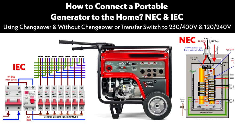
How to Wire a 1-P & 3-P Portable Generator to the Home Supply using Changeover & Without Changeover or Transfer Switch (ATS & MTS) for 230V/400V & 120V/240V
We all suffer from power failure in emergency breakdown (i.e. short circuit, overload, damage to electric transmission lines, substations or other parts of the distribution system as well as storms and other bad weather conditions etc.). In this case, emergency and portable generator can be used to restore the electric power to the home supply and other connected appliances.
In this step by step tutorial, we will be showing the portable generator wiring and connection diagram to the home supply and main distribution board according to NEC and IEC. We will be using Automatic Changeover Switch also known as Automatic Transfer Switch (ATS), Manual Changeover Switch (MTS or Manual Transfer Switch) to connect the generator to a house for 230V and 400V (IEC) and 120V and 240V (NEC). In addition, We will show how to wire a portable generator to home supply without a changeover switch or transfer switches.
By using the following basic electrical wiring installation diagrams for generator connection, you may restore an emergency electric supply in case of power outage by connecting a portable generator (Gas/Petrol/Diesel Generator) to the main distribution board.
Related Posts:
- How to Size a Generator? Portable, Backup & Standby for Home & Commercial Applications
- How to Wire Auto & Manual Changeover & Transfer Switch – (1 & 3 Phase)
So now let’s begin.
We can connect a portable generator to our home supply system by four methods.
Each method with wiring connection and working and operation has been explained in step by step tutorial. (Please read all cautions / warnings, user manual and care must be taken before installing a generator to the home electric power supply system. If you are not sure, contact a licensed electrician to do it properly).
Important Note:
Electricity is our friend as well as the worst enemy, if you give it a chance to kill you, Remember, they will never miss it. Please read all caution and instruction while doing this practical tutorial.
How to Hook Up a Portable Generator to the Home Supply using Manual Changeover & Transfer Switch for 120V, 240V & 230V – NEC & NIEC
Connecting a portable emergency generator to the home power supply system using manual or automatic changeover switches (Auto transfer Switch (ATS) is the safest and recommended method) for 230V (UK & EU – IEC) and 120V/240V (Canada, US – NEC).
Wiring an Emergency Generator Using Manual Changeover Switch 230V – IEC
Steps for Wiring & Installation of a Generator using Manual Changeover Switch
To connect a portable generator to the home electric supply system by manual changeover switch, follow the steps below:
- Install a changeover switch (rated for 63-100A depending on the load) near the main distribution board in the home.
- Connect the main power supply (Line and Neutral) as incoming to the first upper slots of changeover Switch as shown in fig.
- Connect a 6 AWG (7/064″ or 16mm2)” cable wire to the lower two slots of the changeover switch.
- Now connect a 3-pin power socket (for small load) or 32A, 240V power socket – male (for large load) to the 6AVG wire and install onto the wall (near to the generator) and put the generator 3-pin power plug or or 32A, 240V power socket (female) into the power socket which you have installed before.
- You have done and are ready to supply emergency electric power to the home appliances in case of an emergency power blackout.
Related Posts:
- Single Phase Electrical Wiring Installation in Home – NEC & IEC
- Three Phase Electrical Wiring Installation in Home – NEC & IEC
Below is the generator wiring connection diagram to the main distribution board using the manual changeover switch where all the load circuits are connected to the generator supply in case of a power outage. If you don’t need to power up the specific load circuits, you may switch-OFF the related breakers and the rest breakers remain switch-ON. This way, only specific load points can be fed-up through emergency power via generator.
Click image to enlarge

If you want to connect specific load to the generator when utility power goes off i.e. some load on generator and the rest on main power supply as there may be a case where generator may not be able to handle the overall load. You may just switch-off those load points or related circuit breakers to it.
Related Posts:
- How to Wire Single-Phase, 230V Consumer Unit with RCD? IEC, UK & EU
- How to Wire a Garage Consumer Unit?
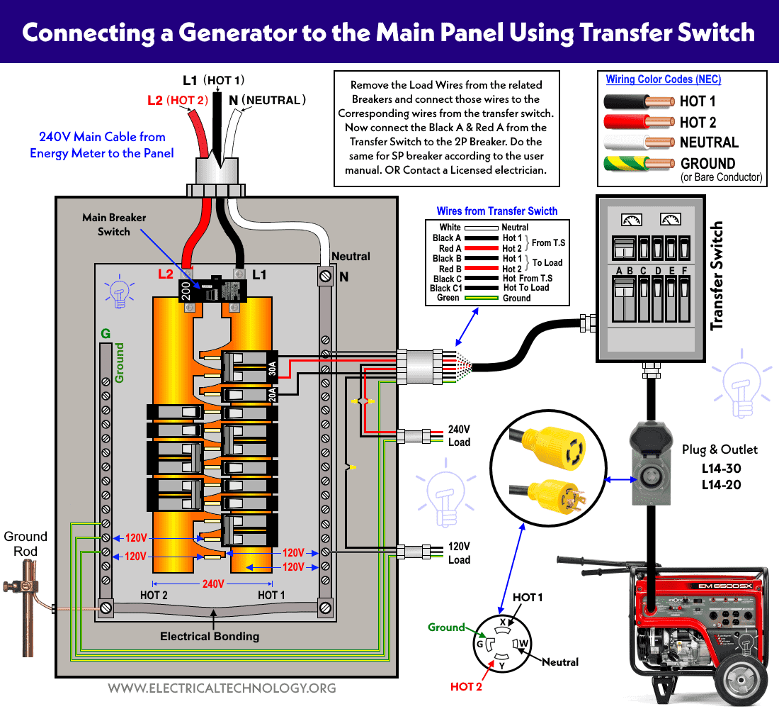
Wiring a Portable Generator Using Manual Transfer Switch for 120 & 240V- NEC
The following wiring diagram shows a portable generator is wired to the 120V/240V main panel using manual transfer switch. Generally, you may connect a 30 amp transfer switch (like Protran or Reliance) for up to 7500 watts generator while other sizes (such as 50 amps) are also available for residential applications.
In this transfer switch, the single pole breaker is 15 amp while the double pole breaker is 30 amp having the max size of 12 gauge wire size.
To do this, just install a 30 amp (or 20 amp depending on the system requirement such as L14-30R, L14-20P) the twist lock plug for extension cord which plug into the generator.
The making of L14-30R, L14-20P plug and outlet indicates the following terminals:
- X = Hot 1 (Black)
- Y = Hot 2 (Red)
- G = Ground
- W = Neutral
Now, to wire the generator and main panel to the transfer switch, Remove the load wires from the related breakers and connect those wires to the corresponding wires from the transfer switch. Now connect the Black A and Red A from the transfer switch to the 2P breaker. Do the same for the SP breaker as shown in below wiring diagram (or according to the user manual). If not sure, contact a licensed electrician.
Click image to enlarge
Related Posts:
- How to Wire 120V & 240V Main Panel? Breaker Box Installation
- How to Wire 208V & 120V, 1-Phase & 3-Phase Main Panel?
When Utility Power is not available, and Generator is ON
The breaker’s switch in the transfer switch pushes one direction and power is connected to the load appliances through Generator → Breaker in the transfer switch → to load points.
The direction of flow of power is followed through wires to the different circuits.
- 120V = Black C1 (to transfer switch) and Black C (from transfer switch) to the load and Neutral wire.
- 240V = Black A & Red A (to transfer switch) and Black B & Red B ( from transfer switch) to the load.
When Utility Power is available, and Generator is OFF
The breaker’s switch in the transfer switch pushes the other direction and power is connected to the load appliances through the main panel → Breaker in the transfer switch → to 120V and 240 load points.
The transfer switch won’t let go the power to energize the generator or power company wires e.g. it turns off the power supply that could come from the breaker in the panel. Keep in mind that only those breakers and load points will work which are connected according to the above (illustrated purpose) wiring diagram.
Related Posts:
- How to Size a Load Center, Panelboards and Distribution Board?
- How to Determine the Number of Circuit Breakers in a Panel Board?
Wiring a Generator Using Manual Transfer Switch for 240V – NEC
The following wiring diagram shows a generator connected to the 120V/240V main panel and 240V load circuits in separate subpanels using a manual transfer switch. These kind of transfer switches (like 2P, GE TC10323R / GE TC35322 / TC10424R or 3P, GE TC35362R emergency power transfer switches and safety switches or disconnectors) are used to connect the generator for power transfer operation or any other appliance for service disconnection as safety switch.
Click image to enlarge
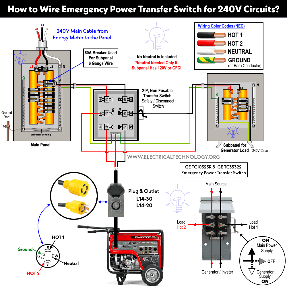
As shown, the generator is connected to the transfer switch through L14-30 (or L14-20) plug and power inlet. The two hot wires (Hot 1 and Hot 2) from the generator are connected to the lower main lugs in the transfer switch.
The upper two hot lugs of the transfer switch are wired to the 60A double pole breaker in the main panel. The center lugs of the transfer switch as load is connected to the 60A subpanel which is designed for 240V load circuits only. As it is a 240V load subpanel, so there is no need for a Neutral wire. Neutral is only required in case of 120V circuits or GFCI/AFCI protected circuits.
The lever operation of the transfer switch is follow:
- UP = Main Supply = ON
- Middle = OFF
- Down = Generator Supply = ON
When the generator is OFF, the lever is on Down position, so the 240V load points are connected to the generator supply, When main supply is available, the lever position is changed to the Up position (manual operation) and the load circuits are fed-up through utility power.
Related Posts:
- How to Wire 240V, 208V & 120V, 1 & 3-Phase, High Leg Delta Main Panel?
- How to Wire 277V & 480V, 1-Phase & 3-Phase, Commercial Main Service Panel?
How to Connect a 1-Phase, 230V Generator to a Home using Automatic Changeover Switch – IEC?
In this way, We have to use a two pole (2P) automatic changeover switch to connect the generator to a home. The connection method is the same as mentioned above for method 1, but we have to use single phase 2 pole automatic changeover instead of manual transfer switch. No hesitation in this way i.e. when the power restores from the utility, the auto transfer switch automatically detects the power and redirects from the generator supply to the main supply and vice versa.
Note: You may use Three Poles (3P) Changeover instead of 2 Poles as well.
Click image to enlarge

Related Posts:
- How to Wire 230V Dual Split Load Consumer Unit? – RCD+MCB
- How to Wire 1-Phase Split Load Consumer Unit? – RCD+RCBO
How to Connect a Portable Generator to a Home without Changeover / Transfer Switch – NEC & IEC
Wiring a Portable Generator without Transfer Switch using Interlock Kit for 120V & 240V – NEC
If you’re looking for a more affordable alternative to a transfer switch for connecting a generator to your home panel, an interlock kit is a practical solution. While you can manually switch off the main breaker and run the generator to power 120V and 240V circuits, it is still safer and highly recommended to use an interlock kit. The interlock kit ensures that the main breaker and the generator breaker cannot be turned on at the same time, preventing backfeeding and enhancing overall safety.
The following wiring diagram shows how to wire an interlock kit for the generator and its operation during the power failure. The interlock kit is installed in the main panel which prevents both (the main and generator breakers at once). Only one breaker (either main or generator) can be ON or OFF at a time by sliding up or down the interlock.
As the generator is wired to the main panel through L14-30 (or L14-20) plug and power inlet and interlock kit in the main panel, let’s see the working operation.
When Utility Power is OFF = Generator is ON
When the main power supply is unavailable, first switch OFF the main breaker and slide the interlock kit up (this locks the main breaker in the OFF position, as shown in the figure). This allows you to start the generator and then switch ON the two-pole (2P) breaker connected to the generator. Once the generator is running and the 2P breaker is ON, you can begin turning ON the 120V and 240V breakers one by one to supply power to the desired load circuits. The red arrow from the generator and power inlet to the 2P breaker and main panel indicates the direction of power flow to the load points.
Related Post:
- How to Determine the Right Size Capacity of a Subpanel?
- How to Wire a Subpanel? Main Lug Installation for 120V/240V
Click image to enlarge
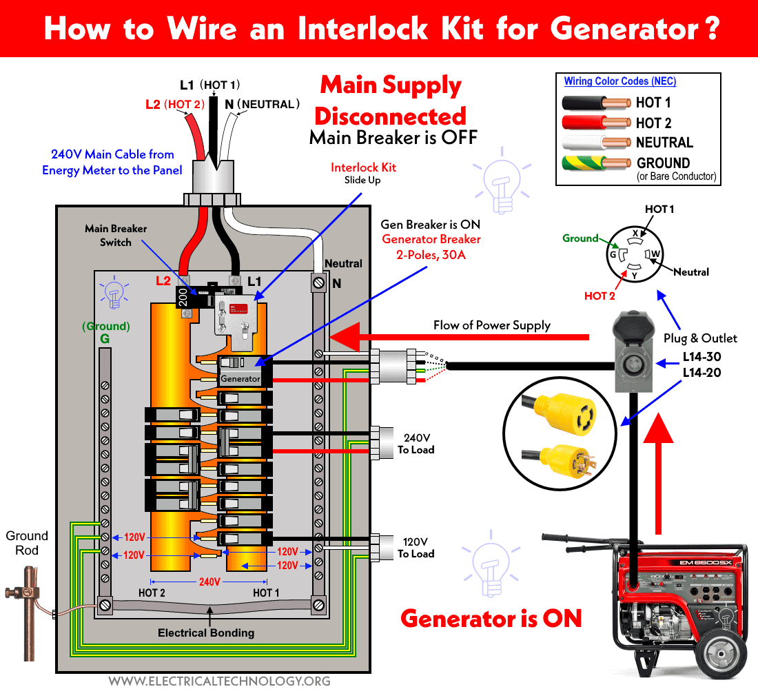
When Utility Power in ON = Generator is OFF
When the utility power is restored, just shut down the generator and switch OFF its related two-pole breaker. Now slide-down the interlock kit (it will prevent switching ON the breaker for generator) which will allow switching ON the main breaker. Just switch ON the main breaker and the supply will restore via main power to the connected load points. The red arrow from the main supply cables shows the power flow to the circuit.
Click image to enlarge
![]()
Related Posts:
- How to Wire Combo Switch and Outlet?
- How to Wire GFCI Combo Switch and Outlet
- How to Wire an AFCI Combo Switch
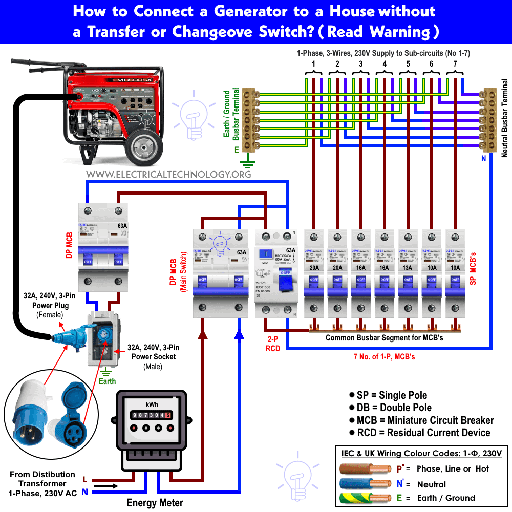
Wiring an Emergency Generator without Changeover Switch for 230V – IEC
Caution: Please follow the local area codes as this method may be not according to the codes in case of IEC following countries. This may lead to serious injuries and hazardous fire as it may be done with special attention as there are chances someone forget to OFF the desired breaker before the operation. In short, it can be done with special care if allowed by the code.
The Installation process and operation is the same as mentioned above but without the Changeover Switch. For this method, switch off both the main switch (MCB) in the distribution board to disconnect the power supply. Now install a separate 63 Amp breaker for the generator (same as main MCB).
Now, connect this new breaker via power inlet (3 Pin power socket or 32A, 230V male power socket) using 6 AWG (7/064″ or 16mm2)”. Finally, connect the 3 pin power plug or 32A, 230V female power plug of the generator in that power inlet or power socket (As shown in below fig). You have done it!
Related Posts:
Click image to enlarge
Operation and Working
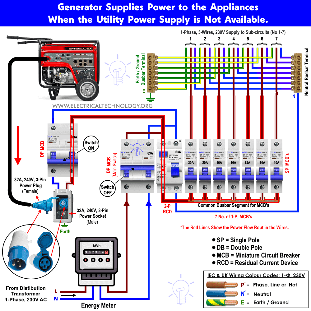
1. In case when utility power supply is not available:
To do this, first of all switch OFF the main breaker and start the generator. Now switch ON the breaker for the generator and switch ON those breakers one by one which connected to the desired load and needed to be operated via emergency power supply from the generator.
When the generator is not in use, FIRST switch OFF the breaker for the generator, switch OFF the generator and then finally, switch ON the main breaker in the distribution board or consumer unit.
In this case, the generator supplies electricity to the home appliances and power flow will continue to those connected electrical appliances and devices through (the Red Line i.e. wires covered in the Red rectangle box) by generator (as shown in below image).
The Red Line in the Red rectangle box) and arrows (↑) shows the power flow in the circuit.
Note: Please! Be Careful.
In this case, the first MCB (Main Switch which is connected to the main power supply) would be “OFF” and the second MCB switch wired for generator) should be “ON”. For extra safety purpose, switch off the 3-pin power socket or 32A generator socket and outlet by switching OFF the built-in ON/OFF button switch when generator is not in used.
Click image to enlarge
Related Posts:
- A Complete Guide About Solar Panel Installation. Step by Step Procedure with Calculation & Diagrams
- How to Wire Batteries in Series, Parallel and Series-Parallel?
- Series, Parallel and Series-Parallel Connection of Solar Panels
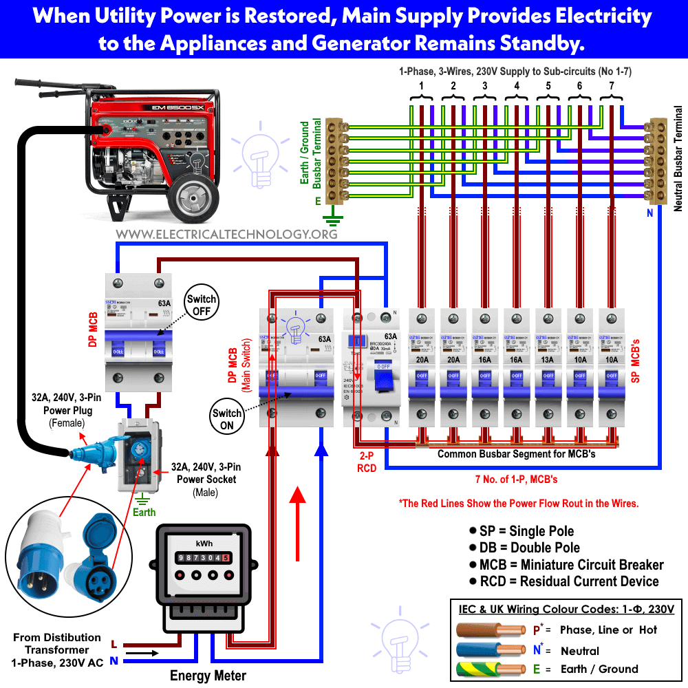
2. In case when power supply restores from power house:
In this case, the main electric lines supply electricity to the home appliances and power flow will continue to those connected electrical appliances in the system through the (the Red Line i.e. wires covered in the Red rectangle box) by main power supply from the power house. Thus, the portable generator remains standby.
Keep in mind that the breaker for the generator will be at OFF position. Never ever switch ON this breaker when main supply is available. For extra safety, switch OFF the power socket by bulletin ON/OFF button or remove the 3-Pin plug for the generator.
Click image to enlarge
Related Posts:
Note: Please! Be Careful.
In this case, the second MCB switch wired for the generator should be “OFF”. For extra safety purposes, switch off the 3-pin power socket or 230V, 32A power outlet and socket by switching OFF the built-in ON/OFF button when the generator is not in use. In addition, shut down the generator and remove the power plug. Now Switch ON the main MCB (Main Switch which is connected to the main power supply).
Cautions And Warnings:
Please read all the given notes, warnings, instructions, manuals and cautions before implementing this method as it may not be legal in some countries due to safety and hazard. Also, It is not recommended for beginners and only a possible way for practical engineers and experienced technicians in case of a very emergency (i.e. power supply failure in hospitals during serious operations) and there is no alternative to restore the power supply.
Only 1 MCB should be “ON” at a time. If the second MCB is “ON” in the above shown figures and operation, i.e. both MSB’s switch “ON” at the same time. Then;
- When utility power is restored from the power house , it may damage your generator or burn the whole system that can cause electric shock & hazard, dangerous fire and explosion at once.
- When main electric supply is not available, generator will send electric supply back into main cables and lines which may overload the generator and may electrocute those linesman & electricians who work/repair in other homes and utility power lines.
- If you don’t have enough practical experience and are not sure about the safety rules provided by the power supplier or generator user manual in your country, don’t practice this method to connect the portable generator to the home supply system. It is also recommended to contact a licensed electrician or power supply company before implementing this method.
Related Posts:
- How to Wire and Install an Electrical Outlet Receptacle?
- How to wire a GFCI Outlet?
- How to Wire an AFCI Outlet?
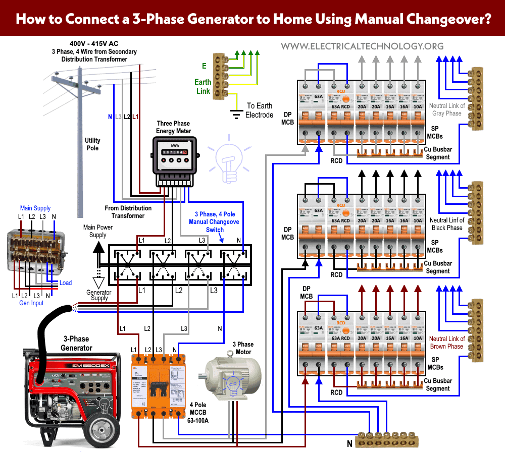
How to Connect a 3-Phase Generator to Home with 4 Pole Automatic Changeover Switch?
To connect a three phase portable generator to the home supply, We have to use a four pole (4P) automatic changeover or transfer switch. The connection method is the same as mentioned above for single phase generator and changeover switch, but we have to use three phase 4 poles manual changeover switch. It is the most reliable and recommended way to connect a generator to the home supply because when the power restores from the utility, the automatic transfer switch automatically detects the power and redirects from the generator supply to the main supply and vice versa.
Note: You may use Three Poles (3P) Auto changeover switch instead if Four Poles (4P) changeover or transfer switch.
Click image to enlarge

How to Connect a 3-Phase Generator to Home with 4 Pole Manual Changeover Switch?
There is no big difference in wiring connections for automatic and manual changeover and transfer switches with portable generators. In the following wiring connection, we have used a four pole manual changeover switch to connect a three phase emergency generator to the distribution boards. The wiring connections for three phase transfer switch are same as wiring for single phase 2 pole changeover switch in method one, while there are another two slots for additional line and neutral as shown in fig below.
Note: You may use Three Poles (3P) Manual changeover switch instead if Four Poles (4P) changeover or transfer switch.
Click image to enlarge
Related Posts:
- How to Wire 1-Phase & 3-Phase Split Load Distribution Board?
- How to Wire Combo of 3 & 1-Φ, 400V/230V Distribution Board?
Wiring Color Code:
We have used the IEC and IEC wiring color codes for 230V/400V and 120V/240V circuits. You may use the local area codes or i IEC – International Electrotechnical Commission (UK, EU etc.) or NEC (National Electrical Code [US & Canada] where;
NEC:
Single Phase 120V AC:
- Black = Hot or Line
- White = Neutral
- Green / Yellow or bare conductor = Ground Wire
Single Phase 240V AC:
- Black = Hot 1 or Line 1
- Red = Hot 2 or Line 2
- White = Neutral
- Green / Yellow or bare conductor = Ground Wire
Three Phase 208 AC:
- Black = Hot 1 or Line 1
- Red = Hot 2 or Line 2
- Blue = Hot 3 or Line 3
- White or Gray = Neutral
- Green / Yellow or bare conductor = Ground Wire
Three Phase 240 AC (High Leg Delta):
- Blue = Hot 1 or Line 1
- Orange = Hot 2 or Line 2 (HIGH LEG DELTA)
- Black = Hot 3 or Line 3
- White or Gray = Neutral
- Green / Yellow or bare conductor = Ground Wire
Three Phase 480V & 600V AC
- Brown = Hot 1 or Line 1
- Orange = Hot 2 or Line 2
- Yellow = Hot 3 or Line 3
- White or Gray = Neutral
- Green / Yellow or bare conductor = Ground Wire
IEC:
Single Phase 230V AC:
- Brown = Phase or Line
- Blue = Neutral
- Green / Yellow = Earth Conductor = Earth Conductor
Three Phase 400V – 415V AC:
- Brown = Phase 1 or Line 1
- Black = Phase 2 or Line 2
- Grey = Phase 3 or Line 3
- Blue = Neutral
- Green / Yellow = Earth Conductor
Related Posts:
General Precaution
General Precautions while playing with Electricity.
- Disconnect the main power source (by switching OFF the main switch in the distribution board / consumer unit and load center / main panel) before servicing, repairing or installing electrical equipment.
- Never try to work on electricity without proper guidance and care.
- Troubleshooting, repairing, installation and modification work related to electricity can be done only in presence of those persons who have good knowledge and practical work and experience who know how to deal with electricity.
- Read all the instructions, user manuals, cautions, local area codes and follow them strictly.
- Doing your own electrical work is dangerous as well as illegal in some areas. Contact the licensed electrician or the power supply company before practicing any change in electrical wiring connection.
- Use the suitable voltage and ampere rating of the switch with appropriate wire size and proper size MCB according to the load rating.
- Switch off the main MCB circuit breaker to make sure the power supply is OFF before wiring an existing or new outlet or switch with an electrical/junction box.
- Contact the authorized and licensed electrician for switch installation if you are not sure about the wiring diagrams.
- The author will not be liable for any losses, injuries, or damages from the display or use of this information or if you try any circuit in the wrong format. So please! Be careful because it’s all about electricity and electricity is too dangerous.
Related Electrical Wiring Installation Tutorials.
- How to Wire a Single Element Water Heater and Thermostat?
- How to Wire 120V Water Heater Thermostat – Non-Simultaneous?
- How to Wire 120V Simultaneous Water Heater Thermostat?
- How to Wire 240V Water Heater Thermostat – Non-Continuous?
- How to Wire 240V Simultaneous Water Heater Thermostat?
- How to Wire 3-Phase Simultaneous Water Heater Thermostat?
- How to Wire 3-Phase Non-Simultaneous Water Heater Thermostat?
- How to Toggle Electric Water Heater Between 120V and 240V?
- Staircase Wiring Circuit Diagram – How to Control a Lamp from 2 Places?
- Corridor Wiring Circuit Diagram – Hallway Wiring using 2-Way Switches
- Tunnel Wiring Circuit Diagram for Light Control using Switches
- Hospital Wiring Circuit for Light Control using Switches
- Hotel Wiring Circuit – Bell Indicator Circuit for Hotelling
- Hostel Wiring Circuit Diagram and Working
- Godown Wiring Diagram – Tunnel Wiring Circuit and Working
- Automatic UPS system wiring circuit diagram for Home or Office
- Manual UPS Wiring Diagram With Change Over Switch System.
- How to Wire 4-Way Switch (NEC) or Intermediate Switch as 3-Way (IEC)?
- How to Wire Single Pole, Single Throw (SPST) as 2-Way Switch?
- How to Wire Single Pole, Double Throw (SPDT) as 3-Way Switch?
- How to Wire Double Pole, Single Throw Switch? Wiring DPST
- How to Wire Double Pole, Double Throw Switch? Wiring DPDT
- How to Wire Double Switch? 2-Gang, 1-Way Switch – IEC & NEC
- How to a Wire 3-Way Combination Switch and Grounded Outlet?
- How to a Wire Double 3-Way Combination Switch Device?
- Even More Residential Wiring Installation Tutorials
-
 How to Install a Wireless Smart Scene Switch
-
 U.S. Data Center Energy Use Could Reach 818 Billion kWh by 2050
-
 U.S. Boneyard Aircraft May Fuel Future AI Data Centers
-
 How to Wire Smart Scene Controller Switch
-
 New French Law Requires Solar Panels Over Parking Areas
-
 New York Imports Record 52 GWh of Canadian Electricity